REMOVAL
Removal / installation · Vehicles built Sep 2011 – Dec 2011
| 1. DISCHARGE FUEL SYSTEM PRESSURE |

Discharge the fuel system pressure (Click here).
| 2. DISCONNECT CABLE FROM NEGATIVE BATTERY TERMINAL |
- NOTICE:
- When disconnect the cable, some systems need to be initialized after the cable is reconnected (Click here).
| 3. REMOVE COWL TOP VENTILATOR LOUVER SUB-ASSEMBLY |
Remove the cowl top ventilator louver sub-assembly (Click here).
| 4. REMOVE FRONT FENDER SPLASH SHIELD SUB-ASSEMBLY LH |
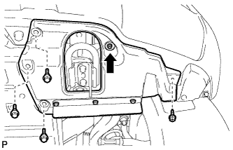  |
Remove the 3 bolts and screw.
Turn the clip indicated by the arrow in the illustration to remove the fender splash shield.
| 5. REMOVE FRONT FENDER SPLASH SHIELD SUB-ASSEMBLY RH |
- HINT:
- Use the same procedures described for the LH side.
| 6. REMOVE NO. 1 ENGINE UNDER COVER SUB-ASSEMBLY |
Remove the 10 bolts and No. 1 engine under cover.
| 7. DRAIN ENGINE COOLANT |
- CAUTION:
- Do not remove the radiator cap while the engine and radiator are still hot. Pressurized, hot engine coolant and steam may be released and cause serious burns.
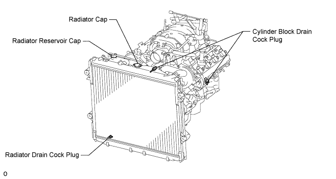
Loosen the radiator drain cock plug.
Remove the radiator cap. Then drain the coolant.
- HINT:
- Collect the coolant in a container and dispose of it according to the regulations in your area.
Loosen the 2 cylinder block drain cock plugs. Then drain the coolant from the engine.
Tighten the 2 cylinder block drain cock plugs.
- Torque:
- 13 N*m{ 130 kgf*cm , 9 ft.*lbf }
Tighten the radiator drain cock plug by hand.
| 8. REMOVE V-BANK COVER SUB-ASSEMBLY |
Remove the 2 nuts and V-bank cover.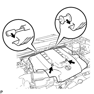
| 9. REMOVE AIR CLEANER HOSE ASSEMBLY |
Disconnect the vacuum transmitting hose and No. 2 ventilation hose.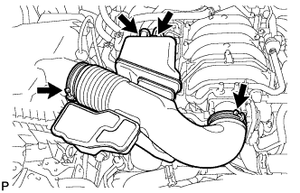
Loosen the 2 hose clamps.
Remove the air cleaner hose.
| 10. REMOVE NO. 2 V-BANK COVER BRACKET |
Remove the 2 bolts and bracket.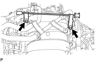
| 11. REMOVE NO. 2 WATER BY-PASS PIPE |
Disconnect the 4 water hoses from the No. 2 water by-pass pipe.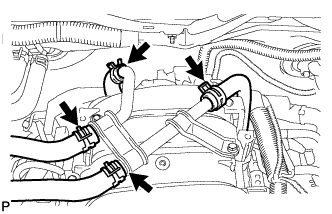
Remove the 2 bolts.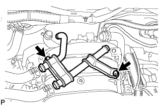
Remove the No. 2 water by-pass pipe.
| 12. DISCONNECT FUEL HOSE |
Remove the fuel hose clamp.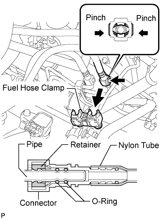
Pinch and pull the fuel hose connector to disconnect the connector from the fuel pipe.
- NOTICE:
- Check for foreign matter in the pipe and around the connector. Clean if necessary. Foreign matter may damage the O-ring or cause leaks in the seal between the pipe and connector.
- Do not use any tools to separate the pipe and connector.
- Do not forcefully bend or twist the nylon tube.
- Check for foreign matter on the pipe seal surface. Clean if necessary.
- Put the pipe and connector ends in plastic bags to prevent damage and foreign matter contamination.
- If the pipe and connector are stuck together, pinch the connector between your fingers and turn it carefully to disconnect it.
- Check for foreign matter in the pipe and around the connector. Clean if necessary. Foreign matter may damage the O-ring or cause leaks in the seal between the pipe and connector.
| 13. REMOVE NO. 2 FUEL HOSE |
for engine side:
Detach the fuel hose clamp.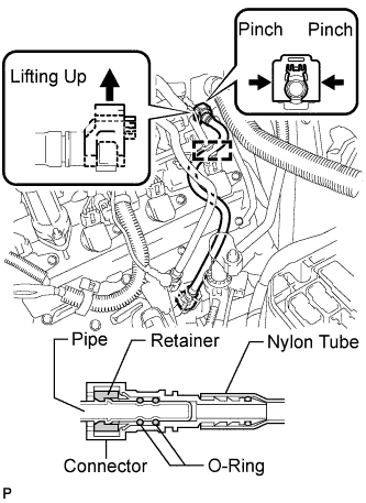
Detach the lock claw by lifting up the cover, as shown in the illustration.
Pinch and pull the No. 2 fuel hose connector to disconnect the connector from the No. 3 fuel pipe.
- NOTICE:
- Check for foreign matter in the pipe and around the connector. Clean if necessary. Foreign matter may damage the O-ring or cause leaks in the seal between the pipe and connector.
- Do not use any tools to separate the pipe and connector.
- Do not forcefully bend or twist the nylon tube.
- Check for foreign matter on the pipe seal surface. Clean if necessary.
- Put the pipe and connector ends in plastic bags to prevent damage and foreign matter contamination.
- If the pipe and connector are stuck together, pinch the connector between your fingers and turn it carefully to disconnect it.
- Check for foreign matter in the pipe and around the connector. Clean if necessary. Foreign matter may damage the O-ring or cause leaks in the seal between the pipe and connector.
for body side:
Pinch and pull the No. 2 fuel hose connector to disconnect the connector from the fuel pipe.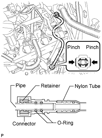
- NOTICE:
- Check for foreign matter in the pipe and around the connector. Clean if necessary. Foreign matter may damage the O-ring or cause leaks in the seal between the pipe and connector.
- Do not use any tools to separate the pipe and connector.
- Do not forcefully bend or twist the nylon tube.
- Check for foreign matter on the pipe seal surface. Clean if necessary.
- Put the pipe and connector ends in plastic bags to prevent damage and foreign matter contamination.
- If the pipe and connector are stuck together, pinch the connector between your fingers and turn it carefully to disconnect it.
- Check for foreign matter in the pipe and around the connector. Clean if necessary. Foreign matter may damage the O-ring or cause leaks in the seal between the pipe and connector.
| 14. REMOVE NO. 2 VENTILATION HOSE |
w/ Secondary Air Injection System: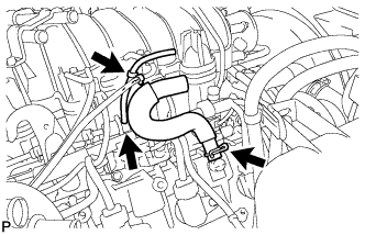
Remove the No. 2 ventilation hose from the cylinder head cover.
Remove the clamp.
Remove the vacuum transmitting hose from the fuel pressure regulator.
w/o Secondary Air Injection System: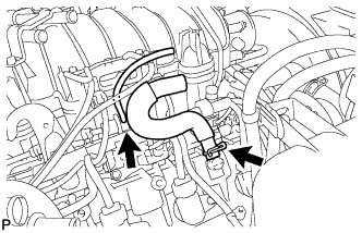
Remove the No. 2 ventilation hose from the cylinder head cover.
Remove the vacuum transmitting hose from the fuel pressure regulator.
| 15. REMOVE VACUUM CONTROL VALVE SET (w/ Secondary Air Injection System) |
Disconnect the 2 VSV connectors.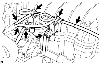
Disconnect the 3 vacuum hoses.
Remove the 2 bolts and vacuum control valve set.
| 16. DISCONNECT NO. 1 WATER BY-PASS HOSE |
Disconnect the No. 1 water by-pass hose from the throttle body.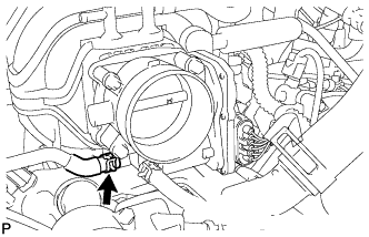
| 17. DISCONNECT NO. 7 WATER BY-PASS HOSE |
Disconnect the No. 7 water by-pass hose from the throttle body.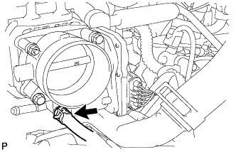
| 18. REMOVE NO. 1 VENTILATION HOSE |
Remove the No. 1 ventilation hose from the intake manifold and ventilation valve.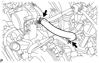
| 19. REMOVE INTAKE MANIFOLD |
Disconnect the throttle position sensor and control motor connector.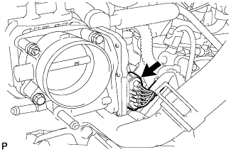
Disconnect the purge VSV connector.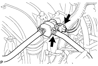
Disconnect the purge line hose from the purge VSV.
Disconnect the VSV connector (for ACIS).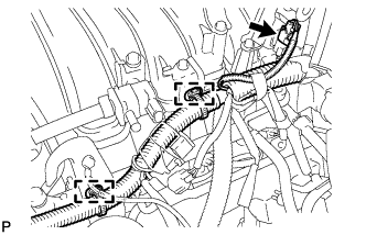
Disconnect the 2 wire clamps from the wire bracket and engine hanger.
Disconnect the 2 wire clamps from the wire clamp brackets on the delivery pipe RH.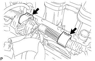
Disconnect the 8 injector connectors.
Remove the 2 bolts and disconnect the engine wire protector.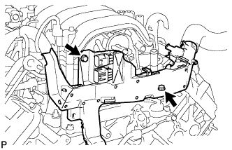
Remove the 6 bolts, 4 nuts, intake manifold and 2 gaskets.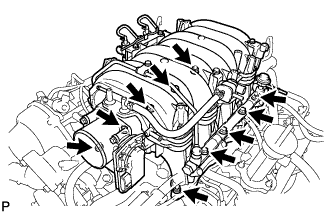
| 20. REMOVE THROTTLE BODY ASSEMBLY |
Remove the nut, 3 bolts, throttle body and gasket.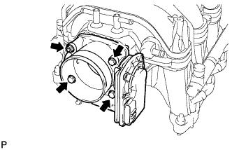
Remove the stud bolt.
| 21. REMOVE PURGE VSV |
Disconnect the purge line hose from the intake manifold.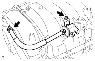
Remove the bolt and purge VSV.
| 22. REMOVE WIRE HARNESS CLAMP BRACKET |
Remove the bolt and bracket.
| 23. REMOVE NO. 4 V-BANK COVER BRACKET |
Remove the bolt and bracket.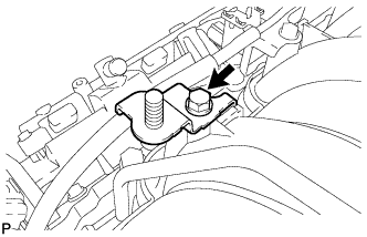
| 24. REMOVE ENGINE COVER JOINT |
Remove the joint from the intake manifold.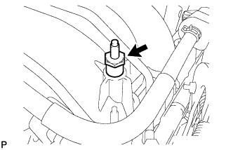
| 25. REMOVE FUEL DELIVERY PIPE SUB-ASSEMBLY |
Remove the 4 nuts holding the delivery pipes to the intake manifold.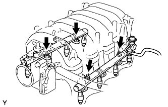
Remove the 2 delivery pipes from the intake manifold.
- NOTICE:
- Be careful not to drop the injectors when removing the delivery pipes.
| 26. REMOVE VACUUM SWITCHING VALVE ASSEMBLY (for ACIS) |
Remove the bolt.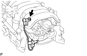
Disconnect the 2 vacuum hoses and VSV connector.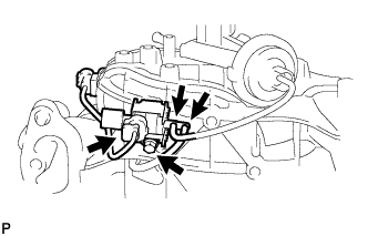
Remove the bolt and VSV.