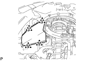
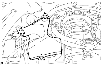
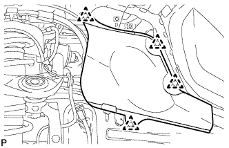
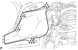
Removal / installation · Vehicles built Sep 2011 – Dec 2011
1.
INSTALL EXHAUST MANIFOLD SUB-ASSEMBLY LH
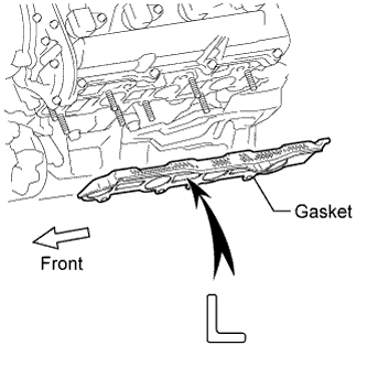
Place a new gasket on the cylinder head with the "L" mark facing the manifold side.
NOTICE:
Be careful of the installation direction.
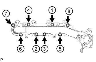
Temporarily install the exhaust manifold with 8 new nuts, and then uniformly tighten the nuts in several steps, in the sequence shown in the illustration.
Torque:
44 N*m{
449 kgf*cm
, 32 ft.*lbf
}
2.
INSTALL NO. 2 EXHAUST MANIFOLD HEAT INSULATOR
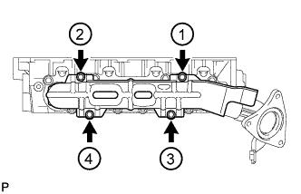
Temporarily install the heat insulator with the 4 bolts.
Uniformly tighten the 4 bolts in several steps, in the sequence shown in the illustration.
Torque:
7.5 N*m{
76 kgf*cm
, 66 in.*lbf
}
3.
INSTALL NO. 2 MANIFOLD STAY
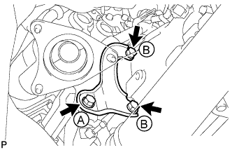
Install the manifold stay with the 3 bolts.
Torque:
for bolt A:
36 N*m{
367 kgf*cm
, 27 ft.*lbf
}
for bolt B:
71 N*m{
724 kgf*cm
, 52 ft.*lbf
}
4.
INSTALL EXHAUST MANIFOLD SUB-ASSEMBLY RH
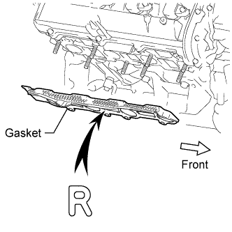
Place a new gasket on the cylinder head with the "R" mark facing the manifold side.
NOTICE:
Be careful of the installation direction.
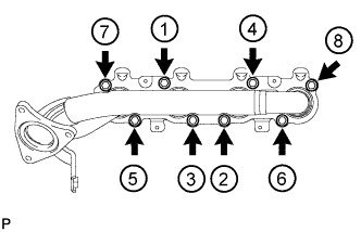
Temporarily install the exhaust manifold with 8 new nuts, and then uniformly tighten the nuts in several steps, in the sequence shown in the illustration.
Torque:
44 N*m{
429 kgf*cm
, 32 ft.*lbf
}
5.
INSTALL NO. 1 EXHAUST MANIFOLD HEAT INSULATOR
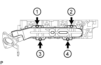
Temporarily install the heat insulator with the 4 bolts.
Uniformly tighten the 4 bolts in several steps, in the sequence shown in the illustration.
Torque:
7.5 N*m{
76 kgf*cm
, 66 in.*lbf
}
6.
INSTALL NO. 1 MANIFOLD STAY
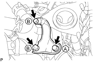
Install the manifold stay with the 3 bolts.
Torque:
for bolt A:
36 N*m{
367 kgf*cm
, 27 ft.*lbf
}
for bolt B:
71 N*m{
724 kgf*cm
, 52 ft.*lbf
}
7.
INSTALL FRONT NO. 2 EXHAUST PIPE ASSEMBLY
Install a new gasket and the front No. 2 exhaust pipe to the exhaust manifold LH with 3 new nuts.
Torque:
54 N*m{
554 kgf*cm
, 40 ft.*lbf
}
Connect the air fuel ratio sensor connector.
Connect the heated oxygen sensor connector.
8.
INSTALL FRONT EXHAUST PIPE ASSEMBLY
Install a new gasket and the front exhaust pipe to the exhaust manifold with 3 new nuts.
Torque:
54 N*m{
554 kgf*cm
, 40 ft.*lbf
}
Connect the air fuel ratio sensor connector.
Connect the heated oxygen sensor connector.
Attach the heated oxygen sensor wire clamp.
9.
INSTALL CENTER EXHAUST PIPE ASSEMBLY
Install the center exhaust pipe to the 3 exhaust pipe supports.
Install 2 new gaskets to the front exhaust pipe and front No. 2 exhaust pipe.
Install the 4 bolts.
Torque:
48 N*m{
489 kgf*cm
, 35 ft.*lbf
}
10.
INSTALL TAILPIPE ASSEMBLY
Install the tailpipe to the 2 exhaust pipe supports.
Install a new gasket to the center exhaust pipe.
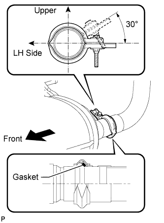
Connect the tailpipe and center exhaust pipe with a new clamp.
Torque:
32 N*m{
326 kgf*cm
, 24 ft.*lbf
}
HINT:
Install the clamp within the angle range shown in the illustration.
11.
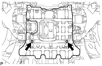
INSTALL NO. 2 ENGINE UNDER COVER
Install the No. 2 engine under cover with the 2 bolts.
Torque:
29 N*m{
296 kgf*cm
, 21 ft.*lbf
}
12.
INSTALL ENGINE OIL LEVEL DIPSTICK GUIDE
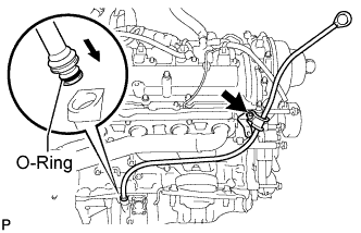
Apply a light coat of engine oil to a new O-ring.
Install a new O-ring to the guide.
Install the dipstick guide with the bolt.
Torque:
8.0 N*m{
82 kgf*cm
, 71 in.*lbf
}
Install the dipstick.
13.
CONNECT COOLER COMPRESSOR
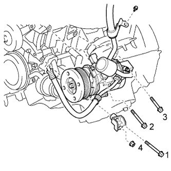
Connect the compressor. Then install it and the No. 1 compressor stay with the nut and 3 bolts.
Torque:
for bolt:
45 N*m{
459 kgf*cm
, 33 ft.*lbf
}
for nut:
25 N*m{
250 kgf*cm
, 18 ft.*lbf
}
HINT:
Tighten the bolts in the order shown in the illustration to install the cooler compressor.
Install the cooler refrigerant suction hose with the bolt.
Torque:
9.8 N*m{
100 kgf*cm
, 87 in.*lbf
}
Connect the connector.
14.
INSPECT FOR EXHAUST GAS LEAK
If gas is leaking, tighten the areas necessary to stop the leak. Replace damaged parts as necessary.