TERMINALS OF ECU
System information · Vehicles built Sep 2011 – Dec 2011
Versions by build date: Sep 2011 – Dec 2011 from Jan 2012
| CHECK AIR CONDITIONING AMPLIFIER (w/ Rear air conditioning amplifier) |
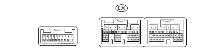

Disconnect the E36 air conditioning amplifier connector.
Measure the resistance and voltage according to the value(s) in the table below.
Terminal No. (Symbol)
Wiring Color
Terminal Description
Condition
Specified Condition
E36-5 (IG+) - E36-1 (GND)
G - W-B
Ignition power supply
Engine switch on (IG)
11 to 14 V
Engine switch off
Below 1 V
E36-6 (+B1) - E36-1 (GND)
R - W-B
Battery power source
Always
11 to 14 V
E36-7 (+B2) - E36-1 (GND)
R - W-B
Battery power source
Always
11 to 14 V
E36-1 (GND) - Body ground
W-B - Body ground
Ground
Always
Below 1 Ω
- If the result is not as specified, there may be a malfunction on the wire harness side.
- If the result is not as specified, there may be a malfunction on the wire harness side.
Reconnect the E36 air conditioning amplifier connector.
Measure the voltage according to the value(s) in the table below.
Terminal No. (Symbol)
Wiring Color
Terminal Description
Condition
Specified Condition
E36-24 (RDEF) - E36-1 (GND)
G - W-B
Defogger relay
Engine switch on (IG) and defogger switch off
11 to 14 V
Engine switch on (IG) and defogger switch on
Below 1 V
- If the result is not as specified, the air conditioning amplifier or fuse may have a malfunction.
- If the result is not as specified, the air conditioning amplifier or fuse may have a malfunction.
| CHECK AIR CONDITIONING AMPLIFIER (w/o Rear air conditioning amplifier) |
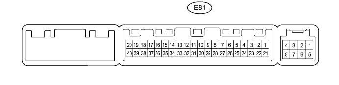
Disconnect the E81 air conditioning amplifier connector.
Measure the resistance and voltage according to the value(s) in the table below.
Terminal No. (Symbol)
Wiring Color
Terminal Description
Condition
Specified Condition
E81-1 (IG+) - E81-14 (GND)
G - W-B
Ignition power supply
Engine switch on (IG)
11 to 14 V
Engine switch off
Below 1 V
E81-21 (+B1) - E81-14 (GND)
R - W-B
Battery power source
Always
11 to 14 V
E81-14 (GND) - Body ground
W-B - Body ground
Ground
Always
Below 1 Ω
- If the result is not as specified, there may be a malfunction on the wire harness side.
- If the result is not as specified, there may be a malfunction on the wire harness side.
Reconnect the E81 air conditioning amplifier connector.
Measure the voltage according to the value(s) in the table below.
Terminal No. (Symbol)
Wiring Color
Terminal Description
Condition
Specified Condition
E81-38 (RDEF) - E81-14 (GND)
G - W-B
Defogger relay
Engine switch on (IG) and defogger switch off
11 to 14 V
Engine switch on (IG) and defogger switch on
Below 1 V
- If the result is not as specified, the air conditioning amplifier or fuse may have a malfunction.
- If the result is not as specified, the air conditioning amplifier or fuse may have a malfunction.
| CHECK AIR CONDITIONING CONTROL ASSEMBLY (w/o Multi-display) |

Disconnect the F10 air conditioning control assembly connector.
Measure the resistance and voltage according to the value(s) in the table below.
Terminal No. (Symbol)
Wiring Color
Terminal Description
Condition
Specified Condition
F10-7 (IG+) - F10-1 (GND)
G - W-B
Ignition power supply
Engine switch on (IG)
11 to 14 V
Engine switch off
Below 1 V
F10-1 (GND) - Body ground
W-B - Body ground
Ground
Always
Below 1 Ω
- If the result is not as specified, there may be a malfunction on the wire harness side.
- If the result is not as specified, there may be a malfunction on the wire harness side.
| CHECK MULTI-DISPLAY |

Disconnect the F64 multi-display connector.
Measure the resistance and voltage according to the value(s) in the table below.
Terminal No. (Symbol)
Wiring Color
Terminal Description
Condition
Specified Condition
F64-3 (IG) - F64-10 (GND1)
G - W-B
Ignition power supply
Engine switch on (IG)
11 to 14 V
Engine switch off
Below 1 V
F64-10 (GND1) - Body ground
W-B - Body ground
Ground
Always
Below 1 Ω
- If the result is not as specified, there may be a malfunction on the wire harness side.
- If the result is not as specified, there may be a malfunction on the wire harness side.