REPLACEMENT
Removal / installation · Vehicles built from Jan 2012
Versions by build date: Sep 2011 – Dec 2011 from Jan 2012
| 1.
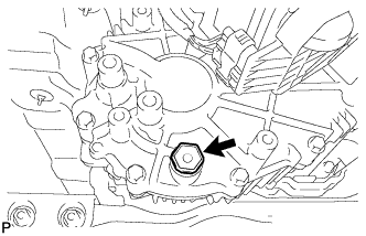
DRAIN TRANSFER OIL
|
 |
- except 1GR-FE:
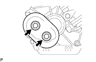
Remove the 2 bolts and transfer dynamic damper.
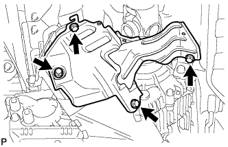
- Remove the 4 bolts and transfer heat insulator.
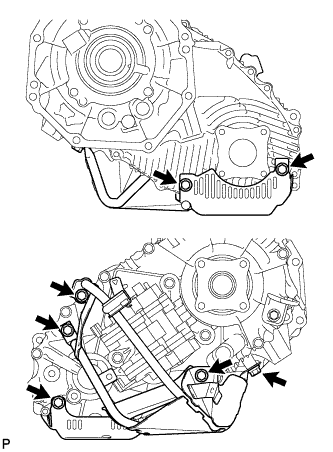
- Remove the 7 bolts and lower transfer case protector.
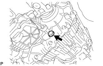
- Remove the filler plug and gasket.
- Remove the drain plug and gasket, and drain the transfer oil.
| 2.
REMOVE FRONT PROPELLER SHAFT ASSEMBLY |
|
(Click here)
| 3.
REMOVE FRONT OUTPUT SHAFT COMPANION FLANGE SUB-ASSEMBLY
|
|
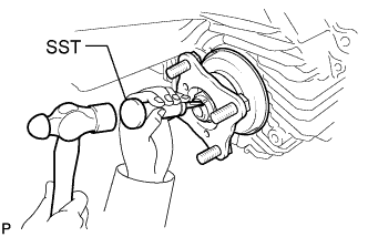
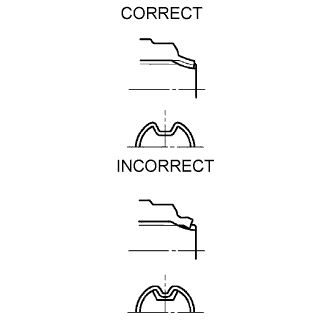
- Using SST and a hammer, release the staked part of the nut.
- SST
- 09930-00010
(09931-00010, 09931-00020)
- NOTICE:
- Be sure to use SST with the tapered surface facing the shaft.
- Do not grind the tip of SST with a grinder, etc.
- Completely loosen the staked part of the nut when removing it.
- Do not damage the threads of the transfer driven sprocket.
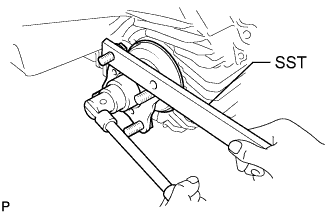
- Using SST to hold the companion flange, remove the lock nut.
- SST
- 09330-00021
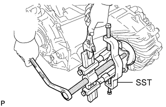
- Using SST, remove the companion flange.
- SST
- 09950-40011
(09951-04020, 09952-04010, 09953-04030, 09954-04010, 09955-04051, 09957-04010, 09958-04011)
Remove the O-ring from the companion flange.
| 4.
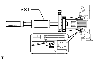
REMOVE TRANSFER CASE FRONT OIL SEAL |
|
- Using SST, tap out the oil seal.
- SST
- 09308-00010
- NOTICE:
- Be careful not to damage the oil seal and front transfer case contact surface.
| 5.
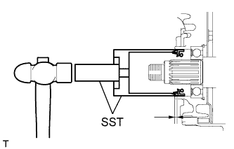
INSTALL TRANSFER CASE FRONT OIL SEAL |
|
Apply transfer oil to the spline of the driven sprocket.
- Using SST and a hammer, tap in a new oil seal until its surface is 1 to 1.5 mm (0.0394 to 0.0590 in.) from the case upper surface.
- SST
- 09649-17010
09950-70010
(09951-07150)
| 6.
INSTALL FRONT OUTPUT SHAFT COMPANION FLANGE SUB-ASSEMBLY
|
|
Install the companion flange onto the drive sprocket.
- Using SST to hold the companion flange, install a new O-ring and a new companion flange lock nut.
- SST
- 09330-00021
-
Torque:
- 127 N*m{
1299 kgf*cm
, 94 ft.*lbf
}
- Using a chisel and hammer, stake the companion flange lock nut.
| 7.
INSTALL FRONT PROPELLER SHAFT ASSEMBLY |
|
(Click here)
| 8.
ADD TRANSFER OIL
|
|
- Install a new gasket onto the drain plug and then install the plug.
-
Torque:
- 37 N*m{
377 kgf*cm
, 27 ft.*lbf
}
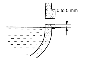
- Add oil so that the oil level is between 0 to 5.0 mm (0 to 0.197 in.) from the bottom lip of the filler plug hole.
- NOTICE:
- Add oil slowly.
- Add oil a little at a time, waiting several minutes between each addition of oil.
Wait approximately 5 minutes and check that the oil level has not changed.
- Install a new gasket onto the filler plug and then install the plug.
-
Torque:
- 37 N*m{
377 kgf*cm
, 27 ft.*lbf
}
- Install the lower transfer case protector with the 7 bolts.
-
Torque:
- 14 N*m{
139 kgf*cm
, 10 ft.*lbf
}
- Install the transfer heat insulator with the 4 bolts.
-
Torque:
- 30 N*m{
306 kgf*cm
, 22 ft.*lbf
}
- except 1GR-FE:
Install the transfer dynamic damper with the 2 bolts.
-
Torque:
- 12 N*m{
122 kgf*cm
, 9 ft.*lbf
}
| 9.
CHECK FOR TRANSFER OIL LEAK |
|