DISASSEMBLY
Removal / installation · Vehicles built from Sep 2011
| 1. INSPECT RUNOUT OF REAR DRIVE PINION COMPANION FLANGE REAR SUB-ASSEMBLY |

Using a dial indicator, measure the vertical and lateral runout of the companion flange.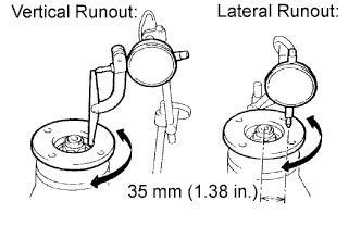

- Maximum Runout:
Runout
Specified Condition
Vertical runout
0.10 mm (0.00394 in.)
Lateral runout
0.10 mm (0.00394 in.)
| 2. INSPECT RUNOUT OF DIFFERENTIAL RING GEAR |
Using a dial indicator, measure the runout of the ring gear.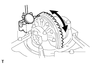
- Maximum runout:
- 0.05 mm (0.00197 in.)
| 3. INSPECT DIFFERENTIAL RING GEAR BACKLASH |
Using a dial indicator, measure the backlash of the ring gear.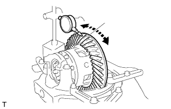
- Standard backlash:
- 0.10 to 0.20 mm (0.00394 to 0.00787 in.)
- HINT:
- Measure at 3 or more positions around the circumference of the ring gear.
| 4. REMOVE NO. 1 TRANSFER INDICATOR SWITCH |
Remove the switch and gasket.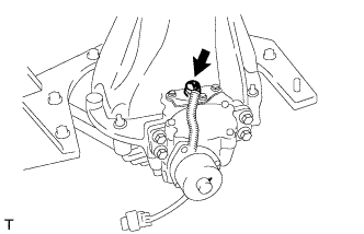
| 5. REMOVE REAR DIFFERENTIAL LOCK COVER |
Remove the 3 bolts.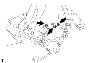
Using a brass bar and hammer, tap on the cover to remove it.
| 6. REMOVE DIFFERENTIAL LOCK SHIFT ACTUATOR |
Remove the 4 bolts.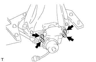
Remove the shift fork shaft bolt.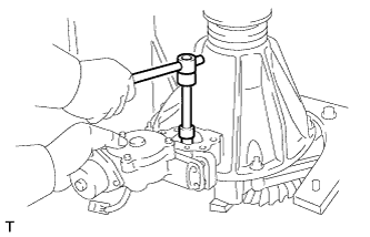
Using a screwdriver, pull out the actuator and remove the sleeve and shift fork.
| 7. REMOVE DRIVE PINION COMPANION FLANGE REAR NUT |
Using SST and a hammer, unstake the nut.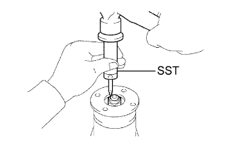
- SST
- 09930-00010
Using SST to hold the companion flange, remove the nut.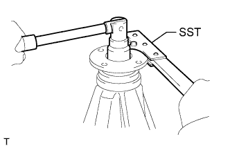
- SST
- 09330-00021
(09330-00030)
| 8. REMOVE REAR DRIVE PINION COMPANION FLANGE REAR SUB-ASSEMBLY |
Using SST, remove the companion flange.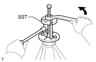
- SST
- 09950-30012
(09951-03010, 09953-03010, 09954-03010, 09956-03030)
| 9. REMOVE REAR DIFFERENTIAL CARRIER OIL SEAL |
Using SST, remove the oil seal.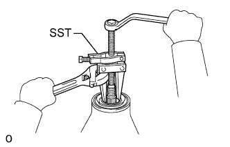
- SST
- 09308-10010
| 10. REMOVE REAR DIFFERENTIAL DRIVE PINION OIL SLINGER |
| 11. REMOVE REAR DRIVE PINION FRONT TAPERED ROLLER BEARING |
Using SST, remove the bearing (inner race).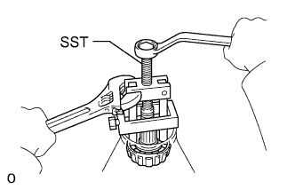
- SST
- 09556-22010
| 12. REMOVE REAR DIFFERENTIAL CASE SUB-ASSEMBLY |
Place matchmarks on the bearing caps and differential carrier.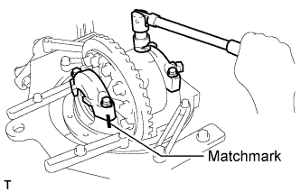
Remove the 4 bolts and 2 bearing caps.
Using SST and a hammer, remove the plate washers.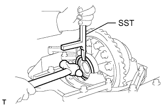
- SST
- 09504-22011
- HINT:
- Measure the thickness of each plate washer and note it down.
Remove the differential case with the side bearing (outer race) from the differential carrier.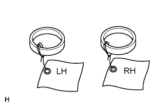
- HINT:
- Tag the bearing outer races to show the location for reassembly.
| 13. REMOVE DIFFERENTIAL DRIVE PINION |
| 14. REMOVE REAR DIFFERENTIAL DRIVE PINION BEARING SPACER |
| 15. REMOVE REAR DRIVE PINION REAR TAPERED ROLLER BEARING |
Using SST and a press, press out the rear bearing (inner race) from the drive pinion.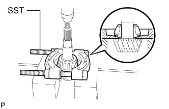
- SST
- 09950-00020
| 16. REMOVE REAR DIFFERENTIAL DRIVE PINION PLATE WASHER |
| 17. REMOVE REAR DRIVE PINION FRONT TAPERED ROLLER BEARING |
Using a brass bar and hammer, tap out the bearing (outer race).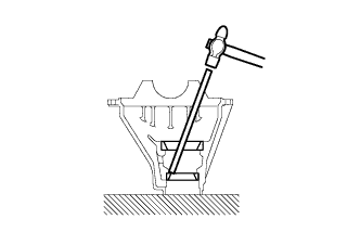
| 18. REMOVE REAR DRIVE PINION REAR TAPERED ROLLER BEARING |
Using a brass bar and hammer, tap out the bearing (outer race).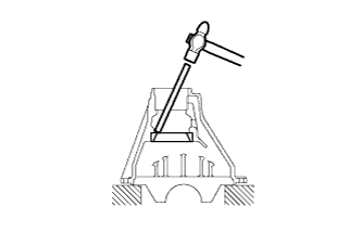
| 19. REMOVE DIFFERENTIAL RING GEAR |
Place matchmarks on the ring gear and differential case.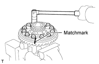
Remove the 12 ring gear set bolts.
Using a plastic-faced hammer, tap on the ring gear to separate it from the differential case.
| 20. INSPECT RUNOUT OF DIFFERENTIAL CASE |
Place the bearing outer races on their respective bearings.
- HINT:
- Do not interchange the left and right outer races.
Install the assembled plate washers to the side bearing.
Install the differential case to the differential carrier.
- HINT:
- If it is difficult to install the differential case to the carrier, replace the plate washer with a thinner one.
Align the matchmarks on the bearing caps and differential carrier.
Install and uniformly tighten the 4 bolts a little at a time.
Using a dial indicator, measure the differential case runout.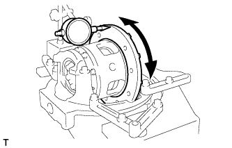
- Maximum case runout:
- 0.04 mm (0.00157 in.)
Remove the differential case.
| 21. DISASSEMBLE DIFFERENTIAL CASE |
Place matchmarks on the differential case and differential cover.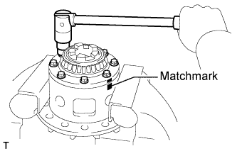
Using a T10 "TORX" socket, remove the 5 set bolts and 3 pinion shaft pins.
Separate the cover and case.
Remove the 2 side gears, 2 side gear thrust washers, 4 pinion gears, 4 pinion gear thrust washers, 3 pinion shafts and holder from the differential case.
| 22. REMOVE REAR DIFFERENTIAL CASE BEARING |
Using SST, remove the side bearing.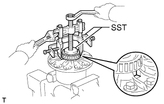
- SST
- 09950-40011
(09952-04010, 09953-04020, 09954-04010, 09955-04061)
- HINT:
- Fix the claws of SST to the notches in the differential case.
| 23. REMOVE REAR DIFFERENTIAL CASE BEARING |
Using SST, 4 bolts and a press, remove the bearing.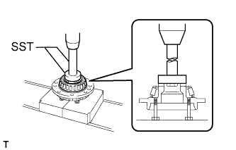
- SST
- 09950-60010
(09951-00580)
09950-70010 (09951-07150)