Removal / installation · Vehicles built from Sep 2011
1.
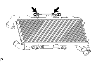
INSTALL ENGINE COVER BRACKET
Install the engine cover bracket with the 2 bolts.
Torque:
9.0 N*m{
92 kgf*cm
, 80 in.*lbf
}
2.
INSTALL INTERCOOLER ASSEMBLY
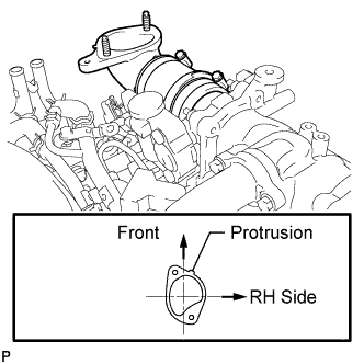
Install a new gasket to the air tube RH.
HINT:
Install the gasket with the protrusion facing as shown in the illustration.
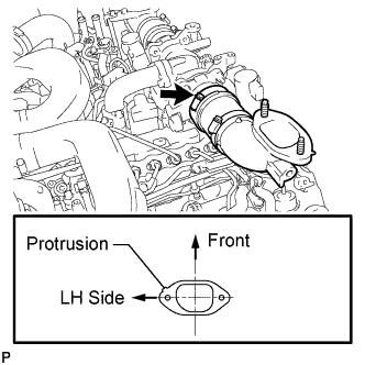
Install a new gasket to the air tube LH.
HINT:
Install the gasket with the protrusion facing as shown in the illustration.
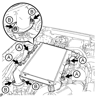
Align the No. 1 and No. 2 air hoses and intercooler pipes and connect them, and install the intercooler with the 2 bolts and 2 nuts labeled A in the illustration.
Torque:
21 N*m{
214 kgf*cm
, 15 ft.*lbf
}
Temporarily install the 4 nuts labeled B in the illustration.
Tighten the air tube LH and RH with the 4 nuts labeled B shown in the illustration.
Torque:
21 N*m{
214 kgf*cm
, 15 ft.*lbf
}
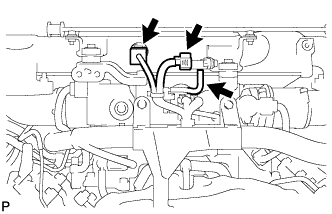
Connect the vacuum hose, intake air temperature sensor connector and turbo pressure sensor connector.
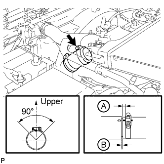
Tighten the clamp of the No. 2 air hose.
Torque:
6.3 N*m{
64 kgf*cm
, 56 in.*lbf
}
HINT:
Align the paint mark of the air hose with the protrusion and push in the air hose so that distance B is 0 to 3 mm (0 to 0.118 in.).
Position the clamp so that distance A is 2 to 6 mm (0.0787 to 0.236 in.).
Make sure the direction of the hose clamp is as shown in the illustration.
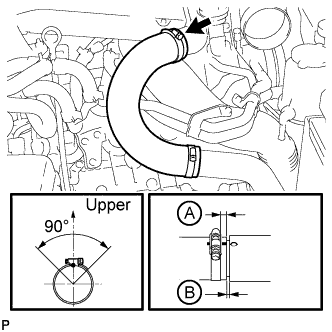
Tighten the clamp of the No. 1 air hose.
Torque:
6.3 N*m{
64 kgf*cm
, 56 in.*lbf
}
HINT:
Align the paint mark of the air hose with the protrusion and push in the air hose so that distance B is 0 to 3 mm (0 to 0.118 in.).
Position the clamp so that distance A is 2 to 6 mm (0.0787 to 0.236 in.).
Make sure the direction of the hose clamp is as shown in the illustration.
3.
INSTALL NO. 1 ENGINE COVER SUB-ASSEMBLY
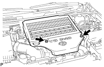
Install the engine cover with the 2 nuts.
Torque:
8.0 N*m{
82 kgf*cm
, 71 in.*lbf
}
4.
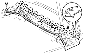
INSTALL COWL TOP VENTILATOR LOUVER SUB-ASSEMBLY
Push the ventilator louver in the direction indicated by the arrow in the illustration to attach the 17 claws and 2 clips and install the ventilator louver.
5.
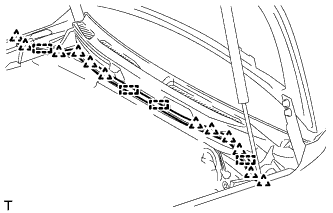
INSTALL HOOD TO COWL TOP SEAL
Attach the 12 clips and 4 clamps to install the hood to cowl top seal.
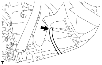
Install the washer hose.
6.
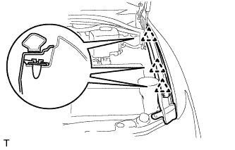
INSTALL FRONT FENDER MAIN SEAL LH
Attach the 3 clips to install the fender main seal.
7.
INSTALL FRONT FENDER MAIN SEAL RH
HINT:
Use the same procedures described for the LH side.
8.
INSTALL FRONT WIPER ARM LH
Stop the wiper motor at the automatic stop position.
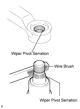
Clean the wiper pivot serration with a wire brush.
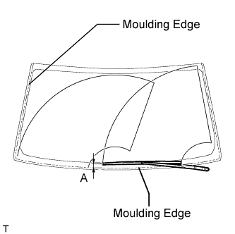
Install the wiper arm and blade with the nut. Make sure that the wiper arm and blade comes to the position shown in the illustration.
Standard Measurement:
Position
Specified Condition
A
16.8 to 36.8 mm (0.661 to 1.45 in.)
Torque:
25 N*m{
255 kgf*cm
, 18 ft.*lbf
}
HINT:
Hold down the wiper arm hinge with your hand while tightening the nut.
9.
INSTALL FRONT WIPER ARM RH
Stop the wiper motor at the automatic stop position.
Clean the wiper pivot serration with a wire brush.
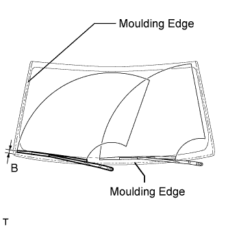
Install the wiper arm and blade with the nut. Make sure that the wiper arm and blade comes to the position shown in the illustration.
Standard Measurement:
Position
Specified Condition
B
20.0 to 40.0 mm (0.787 to 1.57 in.)
Torque:
25 N*m{
255 kgf*cm
, 18 ft.*lbf
}
HINT:
Hold down the wiper arm hinge with your hand while tightening the nut.
Operate the front wipers while spraying washer fluid on the windshield glass. Make sure that the front wipers function properly and there is no interference with the vehicle body.
10.
INSTALL UPPER RADIATOR SUPPORT SEAL
Install the upper radiator support seal with the 7 clips.