Removal / installation · Vehicles built Sep 2011 – Dec 2011
Versions by build date: Sep 2011 – Dec 2011from Jan 2012
1.
DISCONNECT CABLE FROM NEGATIVE BATTERY TERMINAL
CAUTION:
Wait at least 90 seconds after disconnecting the cable from the negative (-) battery terminal to disable the SRS system.
NOTICE:
When disconnect the cable, some systems need to be initialized after the cable is reconnected (Click here).
Disconnect the cables from the negative (-) main battery and sub-battery terminals.
2.
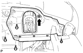
REMOVE FRONT FENDER SPLASH SHIELD SUB-ASSEMBLY LH
Remove the 3 bolts and screw.
Turn the clip indicated by the arrow in the illustration to remove the fender splash shield.
3.
REMOVE FRONT FENDER SPLASH SHIELD SUB-ASSEMBLY RH
HINT:
Use the same procedures described for the LH side.
4.
REMOVE NO. 1 ENGINE UNDER COVER SUB-ASSEMBLY
Remove the 10 bolts and under cover.
5.
REMOVE UPPER RADIATOR SUPPORT SEAL
Remove the 7 clips and upper radiator support seal.
6.
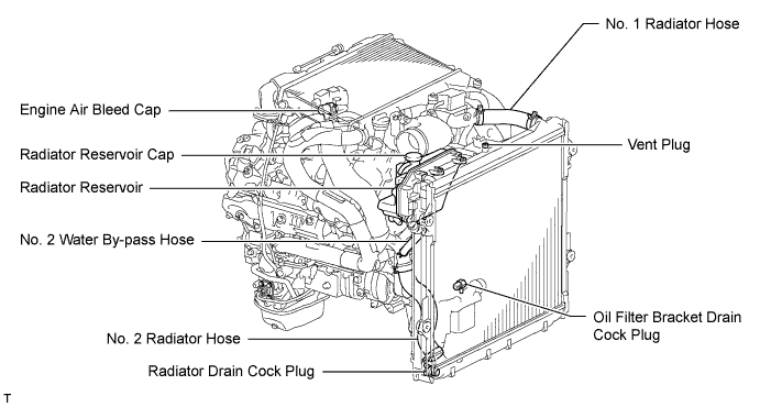
DRAIN ENGINE COOLANT
CAUTION:
Do not remove the radiator reservoir cap while the engine and radiator are still hot. Pressurized, hot engine coolant and steam may be released and cause serious burns.
HINT:
Collect the coolant in a container and dispose of it according to the regulations in your area.
Loosen the radiator drain cock plug.
Remove the radiator reservoir cap to drain the coolant in the radiator.
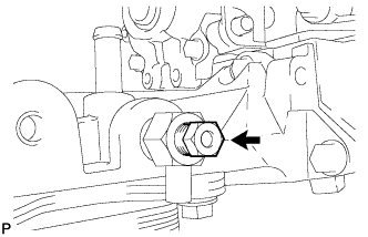
Loosen the oil filter bracket drain cock plug to drain the coolant in the engine.
Tighten the radiator drain cock plug by hand.
Tighten the oil filter bracket drain cock plug.
Torque:
13 N*m{
133 kgf*cm
, 10 ft.*lbf
}
7.
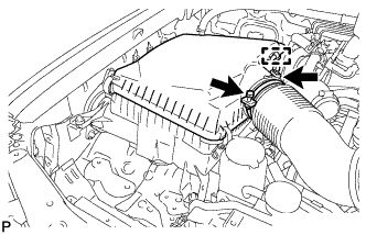
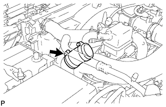
REMOVE AIR CLEANER CAP SUB-ASSEMBLY
Loosen the hose clamp.
Disconnect the mass air flow meter connector and using a clip remover, detach the wire harness clamp from the air cleaner cap.
Detach the 4 clamps and remove the air cleaner cap.
8.
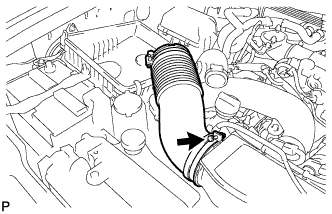
REMOVE NO. 1 AIR CLEANER HOSE
Loosen the hose clamp and remove the No. 1 air cleaner hose.
9.
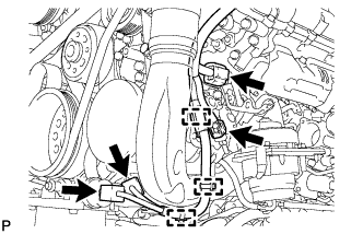
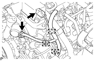
REMOVE INTAKE AIR CONNECTOR
w/o Viscous Heater:
Disconnect the connector from the water temperature sensor.
Using a clip remover, detach the 3 wire harness clamps.
w/ Viscous Heater:
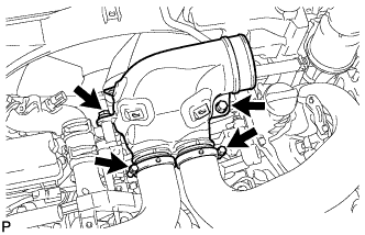
Disconnect the 2 connectors from the viscous with magnet clutch heater and water temperature sensor.
Using a clip remover, detach the 3 wire harness clamps.
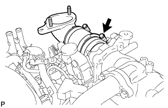
Loosen the 2 hose clamps and remove the 2 bolts and intake air connector.
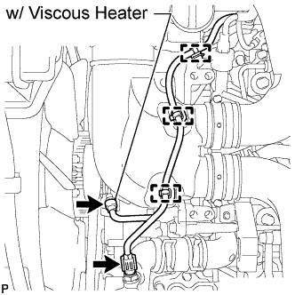
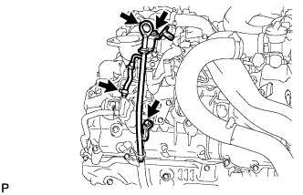
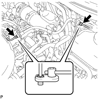
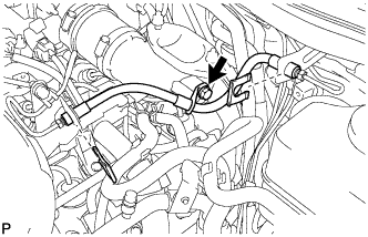
Using a 10 mm union nut wrench, disconnect the tube connector to flexible hose tube from the clutch tube to release cylinder 2 way.
NOTICE:
Do not bend or damage the flexible hose tube.
Do not allow any foreign matter such as dirt and dust to enter the flexible hose tube from the connecting point.
Remove the 2 bolts and tube connector to flexible hose tube.
18.
REMOVE NO. 1 GAS FILTER
Disconnect the hose from the intake pipe.
Remove the gas filter.
19.
REMOVE NO. 3 INTERCOOLER SUPPORT BRACKET
for Manual Transmission:
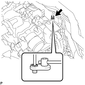
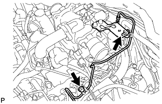
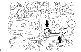
Remove the bolt and disconnect the clutch tube to release cylinder 2 way from the bracket.
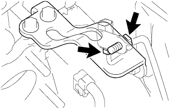
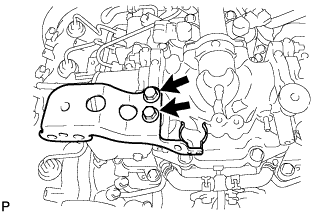
Remove the 2 bolts and bracket.
20.
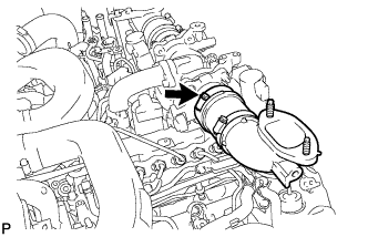
REMOVE DIESEL THROTTLE BODY ASSEMBLY LH
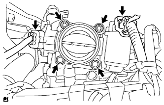
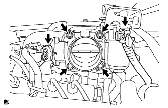
Disconnect the throttle position sensor connector.
Disconnect the throttle motor connector.
Remove the 2 bolts, 2 nuts and throttle body.
Remove the gasket from the intake pipe.
21.
REMOVE NO. 1 AIR HOSE
Loosen the hose clamp and remove the No. 1 air hose.
22.
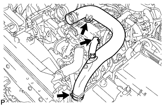
REMOVE NO. 3 AIR TUBE
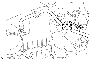
Disconnect the wire harness from the clamp.
Remove the nut and ground wire.
Remove the bolt and disconnect the wire harness bracket.
Loosen the hose clamp and remove the bolt and No. 3 air tube.
23.
REMOVE NO. 2 AIR HOSE
Loosen the hose clamp and remove the No. 2 air hose.
24.
REMOVE NO. 4 AIR TUBE
Remove the bolt and disconnect the suction hose.
Loosen the hose clamp and remove the bolt and No. 4 air tube.
25.
REMOVE NO. 2 AIR CLEANER PIPE SUB-ASSEMBLY
Disconnect the ventilation hose from the oil separator.
Loosen the hose clamp.
Remove the bolt and No. 2 air cleaner pipe.
26.
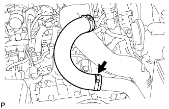
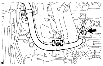
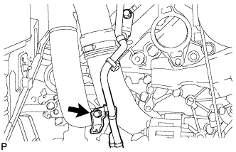
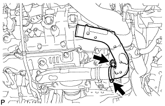
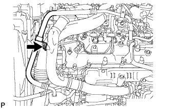
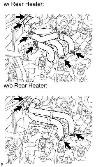
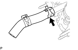
DISCONNECT WATER HOSE SUB-ASSEMBLY
27.
REMOVE HEATER WATER PIPE SUB-ASSEMBLY (w/ Viscous Heater)
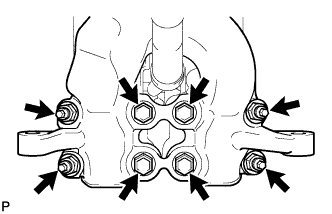
Remove the 4 bolts and disconnect the 4 water hose ends, and then remove the heater water pipe.
28.
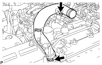
REMOVE NO. 1 AIR CLEANER PIPE SUB-ASSEMBLY
Loosen the hose clamp.
Remove the bolt and No. 1 air cleaner pipe.
29.
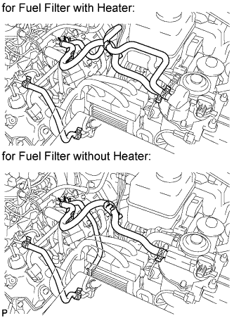
REMOVE FUEL HOSE
30.
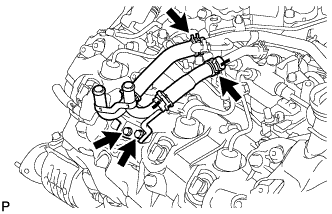
REMOVE NO. 3 WATER BY-PASS PIPE (w/o Viscous Heater)
Remove the 2 bolts and disconnect the 2 water hose ends, and then remove the No. 3 water by-pass pipe.
31.
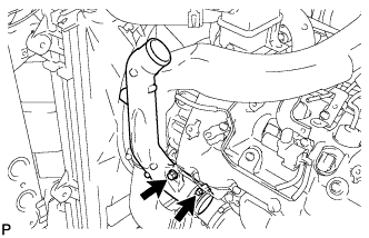
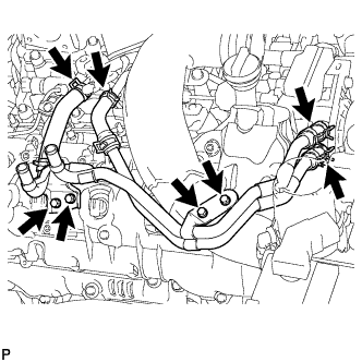
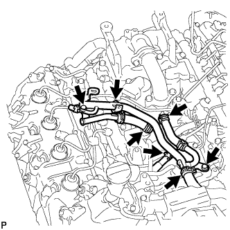
REMOVE NO. 4 WATER BY-PASS PIPE
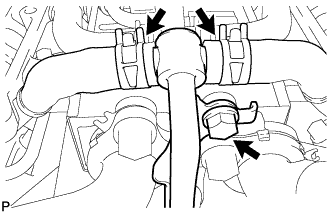
Remove the 2 bolts and nut.
Disconnect the 4 water hose ends, then remove the No. 4 water by-pass pipe.
32.
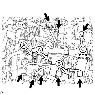
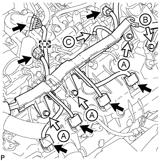
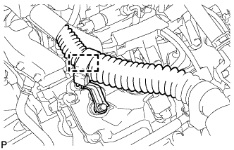
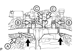
DISCONNECT ENGINE WIRE
LH Side:
Disconnect the 4 connectors.
Using a clip remover, detach the 3 wire harness clamps.
Disconnect the 2 connectors.
Using a clip remover, detach the 3 wire harness clamps.
Disconnect the 8 connectors.
Remove the bolt and engine wire harness bracket labeled B.
Remove the 2 bolts and disconnect the engine wire protector labeled A.
for RHD: Disconnect the wire harness from the wire harness clamp holder labeled C.
RH Side:
Disconnect the 7 connectors.
Using a clip remover, detach the wire harness clamp.
Remove the 3 bolts and disconnect the wire harness protector labeled A.
Remove the bolt and wire harness bracket labeled B.
Remove the nut and glow plug wire harness labeled C.
for RHD: Disconnect the wire harness from the wire harness clamp holder.
Rear Side:
Using a clip remover, detach the wire harness clamp.
Remove the 2 bolts and 2 ground wires labeled C.
Remove the 2 bolts and disconnect the engine wire harness protector labeled B.
Disconnect the 2 common rail connectors.
Remove the nut and disconnect the glow plug wire harness labeled A.
33.
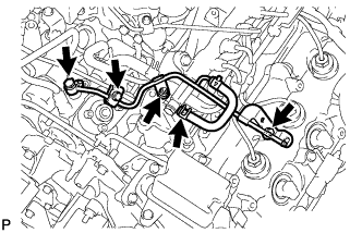
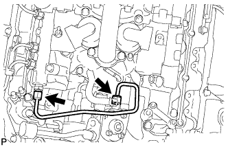
REMOVE NO. 2 FUEL PIPE SUB-ASSEMBLY
NOTICE:
After removing a fuel pipe, to prevent dirt or foreign objects from entering the fuel pipe ends, cover the fuel pipe ends with plastic bags.
After removing a fuel pipe, to prevent dirt or foreign objects from entering the fuel supply pump hole, cover the hole with protective tape.
Disconnect the fuel hose from the No. 5 nozzle leakage pipe.
Remove the bolt and No. 2 injection pipe clamp.
Remove the union bolt and gasket.
Remove the bolt, nut and No. 2 fuel pipe.
34.
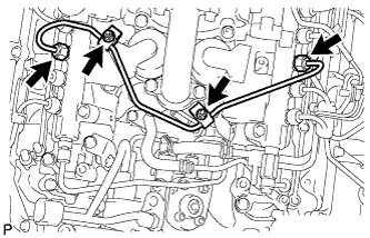
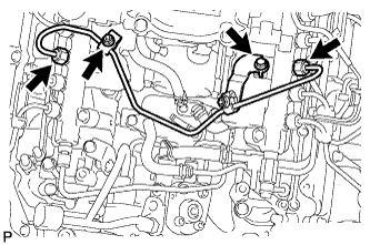
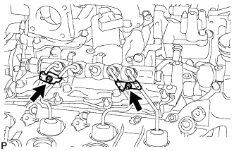
REMOVE NO. 6 INJECTION PIPE SUB-ASSEMBLY
NOTICE:
After removing an injection pipe, to prevent dirt or foreign objects from entering the common rail holes, cover the holes with protective tape.
w/ EGR System:
Using a union nut wrench, loosen the No. 6 injection pipe ends.
Remove the 2 nuts and 2 No. 2 injection pipe clamps.
Remove the No. 6 injection pipe.
w/o EGR System:
Using a union nut wrench, loosen the No. 6 injection pipe ends.
Remove the nut and No. 2 injection pipe clamp.
Remove the bolt and No. 6 injection pipe.
35.
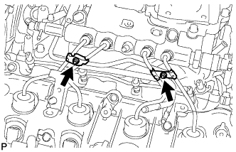
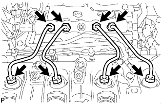
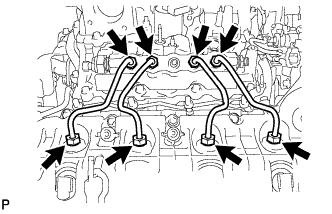
REMOVE INJECTION PIPE LH
w/ Intercooler: Remove the 2 nuts and 4 injection pipe clamps.
Using a union nut wrench, remove the 4 injection pipes.
NOTICE:
After removing an injection pipe, to prevent dirt or foreign objects from entering the common rail holes or injector holes, cover the holes with protective tape.
36.
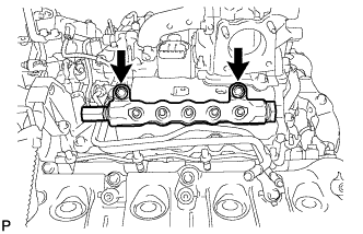
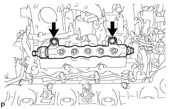
REMOVE COMMON RAIL ASSEMBLY LH
Remove the 2 bolts and common rail.
NOTICE:
Do not remove the fuel pressure limiter from the common rail. If it is removed, replace the common rail.
37.
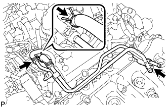
REMOVE FUEL FILTER TO INJECTION PUMP FUEL PIPE SUB-ASSEMBLY
Disconnect the 2 hoses from the fuel pipe.
Remove the bolt and fuel filter to injection pump fuel pipe.
38.
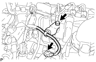
DISCONNECT FUEL PUMP MOTOR WIRE
Remove the bolt and disconnect the connector from the fuel supply pump.
39.
REMOVE NO. 5 INJECTION PIPE SUB-ASSEMBLY
Using a union nut wrench, remove the No. 5 injection pipe.
NOTICE:
After removing an injection pipe, to prevent dirt or foreign objects from entering the common rail hole or injection pump hole, cover the holes with protective tape.
40.
REMOVE INJECTION PIPE RH
w/ Intercooler: Remove the 2 nuts and 4 injection pipe clamps.
Using a union nut wrench, remove the 4 injection pipes.
NOTICE:
After removing an injection pipe, to prevent dirt or foreign objects from entering the common rail holes or injector holes, cover the holes with protective tape.
41.
REMOVE COMMON RAIL ASSEMBLY RH
Remove the 2 bolts and common rail.
NOTICE:
Do not remove the fuel pressure sensor from the common rail. If it is removed, replace the common rail.
42.
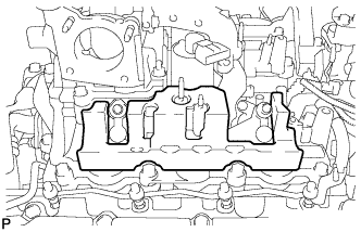
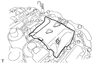
REMOVE NO. 1 INTAKE MANIFOLD INSULATOR
43.
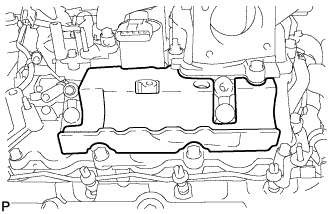
REMOVE NO. 2 INTAKE MANIFOLD INSULATOR
44.
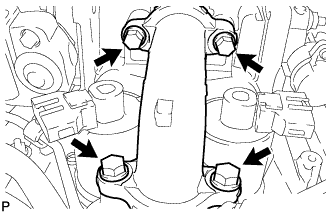
REMOVE NO. 4 EGR PIPE
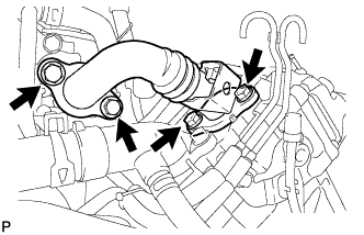
Remove the 4 bolts, EGR pipe and 2 gaskets.
45.
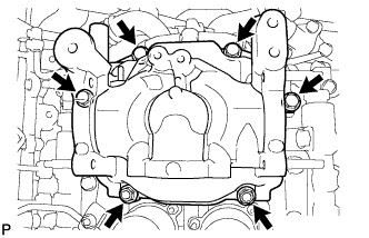
REMOVE INTAKE PIPE
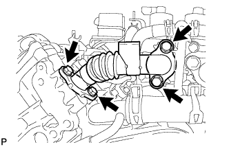
Remove the 4 bolts, 2 nuts and intake pipe.
Remove the gasket.
46.
DISCONNECT NO. 2 ENGINE WIRE
Remove the 3 bolts and using a clip remover, detach the 2 wire harness clamps, and then disconnect the No. 2 engine wire.
47.
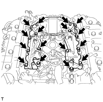
REMOVE NO. 3 INTAKE MANIFOLD
Remove the 16 bolts, No. 3 intake manifold and 2 gaskets.
48.
REMOVE INTAKE MANIFOLD INSULATOR
49.
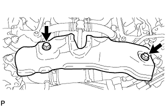
REMOVE EGR PIPE INSULATOR
Remove the 2 bolts and insulator.
50.
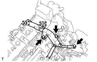
DISCONNECT NO. 5 WATER BY-PASS PIPE
Remove the bolt and disconnect the 2 hoses to disconnect the water by-pass pipe.
51.
REMOVE NO. 1 EGR PIPE SUB-ASSEMBLY
Remove the 4 bolts, EGR pipe and 2 gaskets.
52.
REMOVE NO. 2 EGR PIPE SUB-ASSEMBLY
Remove the 4 bolts, EGR pipe and 2 gaskets.
53.
REMOVE EGR VALVE ASSEMBLY WITH EGR COOLER
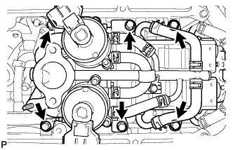
Remove the 6 bolts and EGR valve with EGR cooler.
54.
REMOVE NO. 3 EGR PIPE
Remove the 4 nuts, 4 bolts and pipe.
Remove the 2 gaskets.
55.
REMOVE NO. 4 WATER BY-PASS HOSE
Remove the No. 4 water by-pass hose from the No. 3 water by-pass pipe.
56.
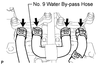
REMOVE NO. 9 WATER BY-PASS HOSE AND WATER HOSE