INSTALLATION
Removal / installation · Vehicles built Sep 2011 – Dec 2011
Versions by build date: Sep 2011 – Dec 2011 from Jan 2012
| 1. INSTALL ENGINE OIL LEVEL SENSOR |

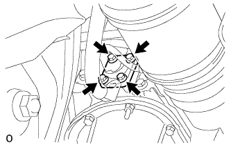  |
Install a new gasket to the sensor.
Install the sensor with the 4 bolts.
- Torque:
- 10 N*m{ 102 kgf*cm , 7 ft.*lbf }
Connect the sensor connector.
| 2. CONNECT OIL COOLER TUBE (for Automatic Transmission) |
Temporarily install the oil cooler tube to the engine with the 2 bolts A and B.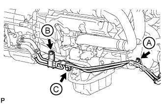
Install the bolt C and tighten it to the specified torque. Then tighten the bolt A and B to the specified torque.
- Torque:
- 14 N*m{ 143 kgf*cm , 10 ft.*lbf }
| 3. ADD ENGINE OIL |
Add fresh oil.
- Standard Engine Oil:
Oil Grade
Oil Viscosity (SAE)
G-DLD-1, API CF-4, API CF or ACEA B1
(You may also use API CE or CD)
- 5W-30
- 10W-30
- 15W-40
- 20W-50
(5W-30 is best choice for fuel economy and good starting in cold weather).
- Standard Capacity:
Item
Specified Condition
Drain and refill with oil filter change
9.2 liters (9.7 US qts, 8.1 Imp. qts)
Drain and refill without oil filter change
8.2 liters (8.7 US qts, 7.2 Imp. qts)
Dry fill
9.9 liters (10.5 US qts, 8.7 Imp. qts)
Install the oil filler cap.
| 4. INSPECT FOR ENGINE OIL LEAK |
Warm up the engine and check for an engine oil leak.
| 5. CHECK ENGINE OIL LEVEL |
Warm up the engine, stop the engine and wait 5 minutes. The engine oil level should be between the dipstick low level mark and full level mark.
If low, check for leakage and add oil up to the full level mark.- NOTICE:
- Do not fill engine oil above the full level mark.
| 6. INSTALL NO. 2 ENGINE UNDER COVER |
Install the engine under cover with the 2 bolts.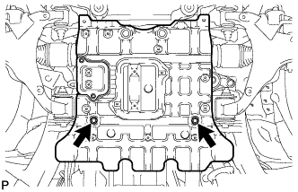
- Torque:
- 29 N*m{ 296 kgf*cm , 21 ft.*lbf }
| 7. INSTALL NO. 1 ENGINE UNDER COVER SUB-ASSEMBLY |
Install the engine under cover with the 10 bolts.
- Torque:
- 29 N*m{ 296 kgf*cm , 21 ft.*lbf }
| 8. INSTALL FRONT FENDER SPLASH SHIELD SUB-ASSEMBLY RH |
- HINT:
- Use the same procedures described for the LH side.
| 9. INSTALL FRONT FENDER SPLASH SHIELD SUB-ASSEMBLY LH |
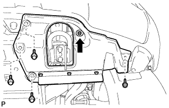 |
Push in the clip indicated by the arrow in the illustration to install the fender splash shield.
Install the 3 bolts and screw.
| 10. INSTALL FRONT FENDER APRON SEAL REAR RH |
Install the front fender apron seal rear RH with the 4 clips.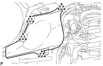
| 11. INSTALL FRONT FENDER APRON SEAL FRONT RH |
Install the front fender apron seal front RH with the 3 clips.
| 12. INSTALL FRONT WHEEL RH |
- Torque:
- for Aluminum Wheel:
- 131 N*m{ 1336 kgf*cm , 97 ft.*lbf }
- for Steel Wheel:
- 209 N*m{ 2131 kgf*cm , 154 ft.*lbf }