Removal / installation · Vehicles built from Sep 2011
1.
INSTALL STARTER CLUTCH SUB-ASSEMBLY
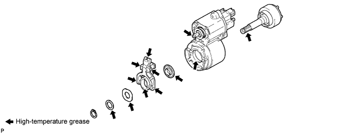
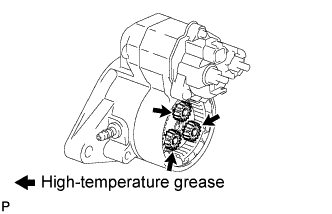
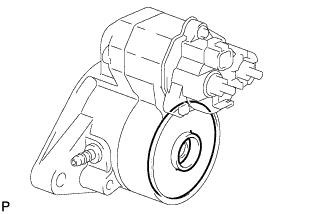
Apply high-temperature grease to the parts indicated by the arrows in the illustration.
Install the starter clutch into the magnet starter switch.
NOTICE:
Make sure that the bearing does not disengage from the starter clutch.
Install the 3 starter washers and pinion drive lever with the snap ring.
2.
INSTALL STARTER DRIVE HOUSING ASSEMBLY
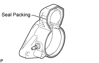
Apply a light coat of seal packing to the surface of the starter drive housing that contacts the starter magnet switch.
Seal packing:
Toyota Genuine Seal Packing 1121C, Three Bond 1121C or equivalent
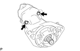
Install the starter drive housing with the 2 bolts.
Torque:
6.0 N*m{
61 kgf*cm
, 53 in.*lbf
}
3.
INSTALL STARTER INTERNAL GEAR
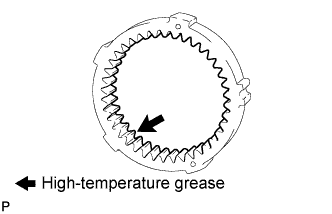
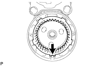
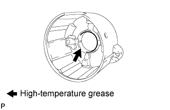
Apply high-temperature grease to the portion indicated by the arrow in the illustration.
Install the starter internal gear.
NOTICE:
Make sure the internal gear protrusion indicated by the arrow in the illustration is aligned with the groove on the bottom side of the magnet starter switch.
Apply high-temperature grease to the planetary gears.
Install the 3 starter planetary gears.
4.
INSTALL STARTER ARMATURE ASSEMBLY
Install the starter washer.
NOTICE:
Make sure that the washer is securely seated in the groove.
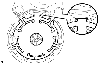
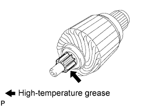
Apply high-temperature grease to the portion indicated by the arrow in the illustration.
Install the starter plate.
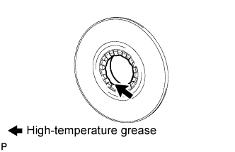
Apply high-temperature grease to the portion indicated by the arrow in the illustration.
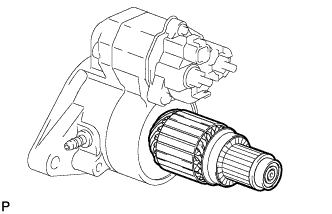
Install the starter armature to the starter plate.
5.
INSTALL STARTER YOKE ASSEMBLY
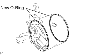
Install 2 new O-rings to the starter yoke.
Install the starter yoke to the magnet starter switch.
6.
INSTALL STARTER BRUSH HOLDER ASSEMBLY
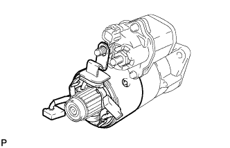
Place the brush holder on the starter armature.
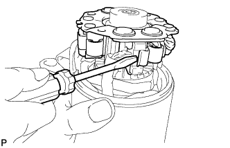
Using a screwdriver, hold the starter brush spring back and connect the 4 starter brushes to the starter brush holder.
NOTICE:
Check that the positive (+) lead wires are not grounded.
Install the starter brush holder into the starter armature.
Apply high-temperature grease to the portion indicated by the arrow in the illustration.
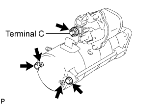
Install the commutator end frame with the 2 screws.
Torque:
3.9 N*m{
40 kgf*cm
, 35 in.*lbf
}
Install the 2 through bolts.
Torque:
17 N*m{
173 kgf*cm
, 12 ft.*lbf
}
Install the nut to terminal C.
Torque:
21 N*m{
214 kgf*cm
, 15 ft.*lbf
}
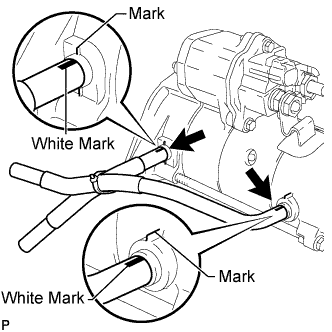
Install the 2 starter hoses to the starter.
7.
INSTALL STARTER CLUTCH PINION
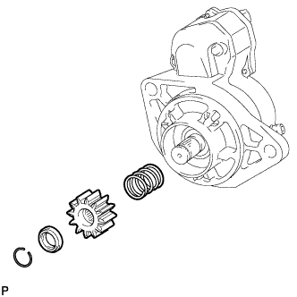
Install the spring, starter clutch pinion and pinion stop collar with the snap ring.