INSTALLATION
Removal / installation · Vehicles built Sep 2011 – Dec 2011
| 1. INSTALL NO. 1 AIR SWITCHING VALVE ASSEMBLY |

Install a new gasket and the No. 1 air switching valve to the rear water by-pass joint with the 2 bolts.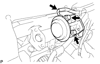

- Torque:
- 10 N*m{ 102 kgf*cm , 7 ft.*lbf }
Connect the vacuum switching valve hose to the No. 1 air switching valve.
| 2. INSTALL NO. 2 AIR SWITCHING VALVE ASSEMBLY |
Install a new gasket and the No. 2 air switching valve to the rear water by-pass joint with the 2 bolts.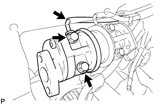
- Torque:
- 10 N*m{ 102 kgf*cm , 7 ft.*lbf }
Connect the vacuum switching valve hose to the No. 2 air switching valve.
| 3. INSTALL NO. 3 AIR TUBE |
Install a new gasket and connect the No. 3 air tube to the exhaust manifold with the 2 nuts.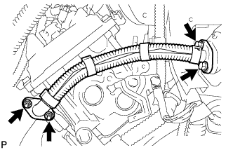
- Torque:
- 10 N*m{ 102 kgf*cm , 7 ft.*lbf }
Install a new gasket and connect the No. 3 air tube to the No. 2 air switching valve with the 2 bolts.
- Torque:
- 10 N*m{ 102 kgf*cm , 7 ft.*lbf }
| 4. INSTALL AIR TUBE SUB-ASSEMBLY RH |
Install a new gasket and connect the air tube to the exhaust manifold with the 2 nuts.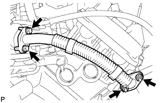
- Torque:
- 10 N*m{ 102 kgf*cm , 7 ft.*lbf }
Install a new gasket and connect the air tube to the No. 1 air switching valve with the 2 bolts.
- Torque:
- 10 N*m{ 102 kgf*cm , 7 ft.*lbf }
| 5. CONNECT NO. 1 WATER BY-PASS PIPE (w/o Air Cooled Transmission Oil Cooler) |
Connect the water by-pass pipe to the cylinder head cover RH with the 2 bolts.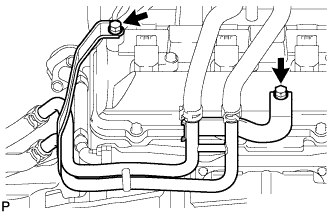
- Torque:
- 18 N*m{ 184 kgf*cm , 13 ft.*lbf }
| 6. INSTALL AIR SWITCHING VALVE ASSEMBLY |
Install the air switching valve to the No. 1 air injection system hose.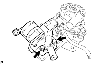
Install the air switching valve to the air pump bracket with the 2 bolts.
- Torque:
- 16 N*m{ 163 kgf*cm , 12 ft.*lbf }
Install the air pressure sensor to the air switching valve with the 2 bolts.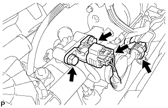
- Torque:
- 5.0 N*m{ 51 kgf*cm , 44 in.*lbf }
Install the vacuum hose to the air pressure sensor and air switching valve.
Connect the air pressure sensor connector.
Connect the air switching valve connector.
| 7. INSTALL NO. 2 AIR INJECTION SYSTEM HOSE |
Install the hose.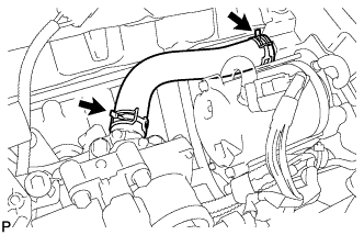
| 8. INSTALL WATER BY-PASS PIPE SUB-ASSEMBLY |
Apply soapy water to the O-ring.
Install a new O-ring to the water by-pass pipe.
Push in the water by-pass pipe.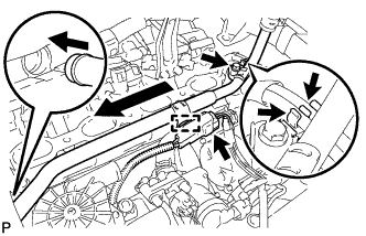
Install the water by-pass pipe with the bolt.
- Torque:
- 18 N*m{ 184 kgf*cm , 13 ft.*lbf }
Connect the 2 vacuum switching valve hoses to the water by-pass pipe clamp.
Connect the wire harness clamp.
Connect the connector.
| 9. INSTALL INTAKE MANIFOLD |
Install the intake manifold (Click here).
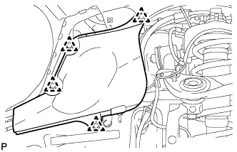
| 10. INSTALL FRONT FENDER APRON SEAL REAR LH |
Install the fender apron seal with the 4 clips.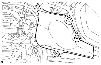
| 11. INSTALL FRONT FENDER APRON SEAL REAR RH |
Install the fender apron seal with the 4 clips.