REPLACEMENT
Removal / installation · Vehicles built from Jan 2012
| 1. DISCHARGE FUEL SYSTEM PRESSURE |

- CAUTION:
- Do not disconnect any part of the fuel system until you have discharged the fuel system pressure.
- After discharging the fuel pressure, place a cloth or equivalent over fittings as you separate them to reduce the risk of fuel spray on yourself or in the engine compartment.
- Do not disconnect any part of the fuel system until you have discharged the fuel system pressure.
Disconnect the fuel pump ECU connector (Click here).
Start the engine. After the engine stops, turn the engine switch off.
- HINT:
- DTC P0171/0174 (system too lean) may be stored.
Crank the engine again, and then check that the engine does not start.
Loosen the fuel tank cap, and then discharge the pressure in the fuel tank completely.
Disconnect the cable from the negative (-) battery terminal.
- NOTICE:
- After turning the engine switch off, waiting time may be required before disconnecting the cable from the battery terminal. Therefore, make sure to read the disconnecting the cable from the battery terminal notice before proceeding with work (Click here).
- When disconnecting the cable, some systems need to be initialized after the cable is reconnected (Click here).
- After turning the engine switch off, waiting time may be required before disconnecting the cable from the battery terminal. Therefore, make sure to read the disconnecting the cable from the battery terminal notice before proceeding with work (Click here).
Connect the fuel pump ECU connector (Click here).
| 2. PRECAUTION |
- NOTICE:
- After turning the engine switch off, waiting time may be required before disconnecting the cable from the battery terminal. Therefore, make sure to read the disconnecting the cable from the battery terminal notice before proceeding with work (Click here).
| 3. DISCONNECT CABLE FROM NEGATIVE BATTERY TERMINAL |
- NOTICE:
- When disconnecting the cable, some systems need to be initialized after the cable is reconnected (Click here).
| 4. REMOVE NO. 1 FUEL TUBE PROTECTOR |
Remove the 4 bolts and No. 1 fuel tube protector.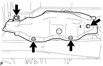

| 5. DISCONNECT NO. 2 FUEL MAIN TUBE SUB-ASSEMBLY |
Pull up the retainer and disconnect the No. 2 fuel main tube.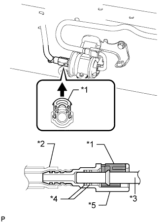
- NOTICE:
- Check for foreign matter in the pipe and around the connector. Clean if necessary. Foreign matter may damage the O-ring or cause leaks in the seal between the pipe and connector.
- Do not use any tools to separate the pipe and connector.
- Do not forcefully bend or twist the nylon tube.
- Check for foreign matter on the pipe seal surface. Clean if necessary.
- Put the pipe and connector ends in plastic bags to prevent damage and foreign matter contamination.
- If the pipe and connector are stuck together, pinch the connector between your fingers and turn it carefully to disconnect it.
- Check for foreign matter in the pipe and around the connector. Clean if necessary. Foreign matter may damage the O-ring or cause leaks in the seal between the pipe and connector.
Text in Illustration *1
Retainer
*2
Nylon Tube
*3
Pipe
*4
O-Ring
*5
Connector
| 6. DISCONNECT FUEL MAIN TUBE |
Pull up the retainer and disconnect the fuel main tube.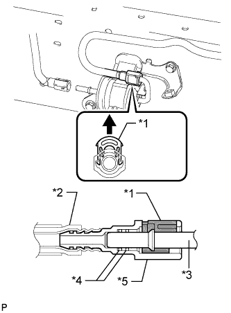
- NOTICE:
- Check for foreign matter in the pipe and around the connector. Clean if necessary. Foreign matter may damage the O-ring or cause leaks in the seal between the pipe and connector.
- Do not use any tools to separate the pipe and connector.
- Do not forcefully bend or twist the nylon tube.
- Check for foreign matter on the pipe seal surface. Clean if necessary.
- Put the pipe and connector ends in plastic bags to prevent damage and foreign matter contamination.
- If the pipe and connector are stuck together, pinch the connector between your fingers and turn it carefully to disconnect it.
- Check for foreign matter in the pipe and around the connector. Clean if necessary. Foreign matter may damage the O-ring or cause leaks in the seal between the pipe and connector.
Text in Illustration *1
Retainer
*2
Nylon Tube
*3
Pipe
*4
O-Ring
*5
Connector
| 7. REMOVE FUEL FILTER ASSEMBLY |
Remove the 2 bolts and fuel filter.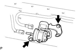
| 8. INSTALL FUEL FILTER ASSEMBLY |
Install the fuel filter with the 2 bolts.
- Torque:
- 20 N*m{ 199 kgf*cm , 14 ft.*lbf }
| 9. CONNECT FUEL MAIN TUBE |
Connect the fuel main tube and push the retainer.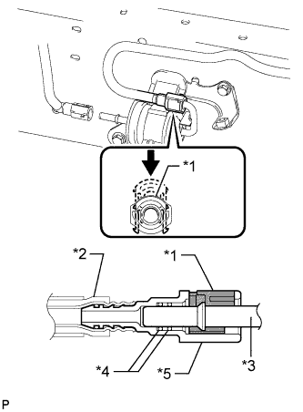
- NOTICE:
- Before installing the tube connectors to the pipes, check if there is any damage or foreign matter in the connectors.
- After the connection, check if the connectors and pipes are securely connected by trying to pull them apart.
- Before installing the tube connectors to the pipes, check if there is any damage or foreign matter in the connectors.
Text in Illustration *1
Retainer
*2
Nylon Tube
*3
Pipe
*4
O-Ring
*5
Connector
- HINT:
- Push the parts together firmly until a "click" sound is heard.
| 10. CONNECT NO. 2 FUEL MAIN TUBE SUB-ASSEMBLY |
Connect the No. 2 fuel main tube and push the retainer.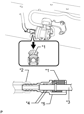
- NOTICE:
- Before installing the tube connectors to the pipes, check if there is any damage or foreign matter in the connectors.
- After the connection, check if the connectors and pipes are securely connected by trying to pull them apart.
- Before installing the tube connectors to the pipes, check if there is any damage or foreign matter in the connectors.
Text in Illustration *1
Retainer
*2
Nylon Tube
*3
Pipe
*4
O-Ring
*5
Connector
- HINT:
- Push the parts together firmly until a "click" sound is heard.
| 11. CONNECT CABLE TO NEGATIVE BATTERY TERMINAL |
- NOTICE:
- When disconnecting the cable, some systems need to be initialized after the cable is reconnected (Click here).
| 12. INSPECT FOR FUEL LEAK |
Make sure that there are no fuel leaks after performing maintenance on the fuel system.
Connect the GTS to the DLC3.
Turn the engine switch on (IG) and turn the GTS on.
- NOTICE:
- Do not start the engine.
Enter the following menus: Powertrain / Engine and ECT / Active Test / Control the Fuel Pump / Speed.
Check that there are no leaks from the fuel system.
If there are fuel leaks, repair or replace parts as necessary.Turn the engine switch off.
Disconnect the GTS from the DLC3.
| 13. INSTALL NO. 1 FUEL TUBE PROTECTOR |
Install the No. 1 fuel tube protector with the 4 bolts.
- Torque:
- 29 N*m{ 296 kgf*cm , 21 ft.*lbf }