INSTALLATION
Removal / installation · Vehicles built from Sep 2011
| 1. INSTALL DIFFERENTIAL LOCK SHIFT ACTUATOR |

Remove any old FIPG material.
Clean the contact surfaces of any residual FIPG material using non-residue solvent.
Apply seal packing to the actuator.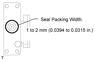

- Seal packing:
- Toyota Genuine Seal Packing 1281, Three Bond 1281 or equivalent:
- HINT:
- Install the actuator within 10 minutes after applying seal packing.
Install the shift fork and actuator to the differential and align the shift fork hole with the shift lock.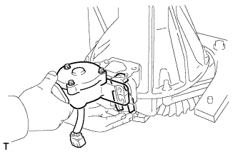
Clean the threads of the set bolt and fork shaft with non-residue solvent.
Coat the threads of the set bolt with adhesive.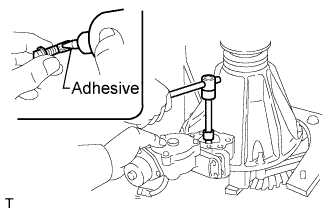
- Adhesive:
- Toyota Genuine Adhesive 1324, Three Bond 1324 or equivalent
Install the shift fork shaft set bolt.
- Torque:
- 20 N*m{ 204 kgf*cm , 15 ft.*lbf }
Engage the sleeve with the dog clutch of the differential case.
Install the 4 bolts.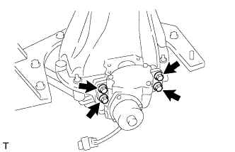
- Torque:
- 24 N*m{ 245 kgf*cm , 18 ft.*lbf }
| 2. INSTALL REAR DIFFERENTIAL LOCK COVER WITH POSITION SWITCH |
Remove any old FIPG material.
Clean the contact surfaces of any residual FIPG material using non-residue solvent.
Apply seal packing to the cover.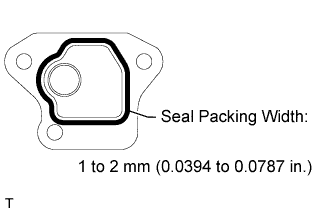
- Seal packing:
- Toyota Genuine Seal Packing 1281, Three Bond 1281 or equivalent
- HINT:
- Install the cover within 10 minutes after applying seal packing.
Install the cover with the 3 bolts.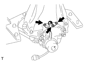
- Torque:
- 18 N*m{ 184 kgf*cm , 13 ft.*lbf }
| 3. INSTALL REAR DIFFERENTIAL LOCK ACTUATOR PROTECTOR |
Install the protector with the 2 nuts.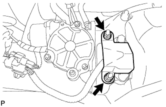
- Torque:
- 35 N*m{ 357 kgf*cm , 26 ft.*lbf }
| 4. INSTALL DIFFERENTIAL PROTECTOR ASSEMBLY |
Attach the protector with the bolt and nut.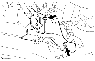
- Torque:
- 15 N*m{ 150 kgf*cm , 11 ft.*lbf }
Connect the 2 connector clamps and wire harness clamp.
- NOTICE:
- Make sure the wire harness of the No. 4 transfer indicator switch fits inside the protector.