INSTALLATION
Removal / installation · Vehicles built Sep 2011 – Dec 2011
Versions by build date: Sep 2011 – Dec 2011 from Jan 2012
- CAUTION:
- Wear protective gloves and protective glasses when installing the exhaust pipe.
- The exhaust pipe is extremely hot immediately after the engine has stopped.
- Confirm that the exhaust pipe has cooled down before removing it.
- Wear protective gloves and protective glasses when installing the exhaust pipe.
| 1. INSTALL OUTLET TURBINE ELBOW LH (w/o Monolithic Converter) |

Set a new gasket to the turbocharger.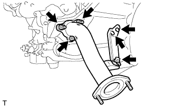

Temporarily install the outlet turbine elbow LH with 3 new nuts.
Temporarily install the manifold stay LH with the 3 bolts.
Tighten the 3 nuts of the outlet turbine elbow LH.
- Torque:
- 47 N*m{ 479 kgf*cm , 35 ft.*lbf }
Tighten the 3 bolts of the manifold stay LH.
- Torque:
- 43 N*m{ 438 kgf*cm , 32 ft.*lbf }
| 2. INSTALL OUTLET TURBINE ELBOW RH (w/o Monolithic Converter) |
Set a new gasket to the turbocharger.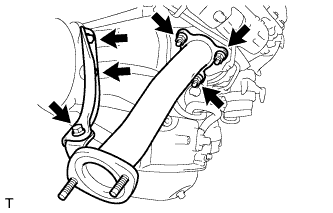
Temporarily install the outlet turbine elbow RH with 3 new nuts.
Temporarily install the manifold stay RH with the 3 bolts.
Tighten the 3 nuts of the outlet turbine elbow RH.
- Torque:
- 47 N*m{ 479 kgf*cm , 35 ft.*lbf }
Tighten the 3 bolts of the manifold stay RH.
- Torque:
- 43 N*m{ 438 kgf*cm , 32 ft.*lbf }
| 3. INSTALL MONOLITHIC CONVERTER ASSEMBLY LH (w/ Monolithic Converter) |
Set a new gasket to the turbocharger.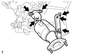
Temporarily install the monolithic converter LH with 3 new nuts.
Temporarily install the manifold stay LH with the 3 bolts.
Tighten the 3 nuts of the monolithic converter LH.
- Torque:
- 47 N*m{ 479 kgf*cm , 35 ft.*lbf }
Tighten the 3 bolts of the manifold stay LH.
- Torque:
- 43 N*m{ 438 kgf*cm , 32 ft.*lbf }
| 4. INSTALL MONOLITHIC CONVERTER ASSEMBLY RH (w/ Monolithic Converter) |
Set a new gasket to the turbocharger.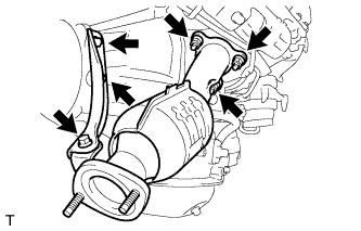
Temporarily install the monolithic converter RH with 3 new nuts.
Temporarily install the manifold stay RH with the 3 bolts.
Tighten the 3 nuts of the monolithic converter RH.
- Torque:
- 47 N*m{ 479 kgf*cm , 35 ft.*lbf }
Tighten the 3 bolts of the manifold stay RH.
- Torque:
- 43 N*m{ 438 kgf*cm , 32 ft.*lbf }
| 5. INSTALL FRONT NO. 2 EXHAUST PIPE ASSEMBLY |
Install a new gasket and the front No. 2 exhaust pipe to the monolithic converter/outlet turbine elbow with 2 new nuts.
- Torque:
- 54 N*m{ 554 kgf*cm , 40 ft.*lbf }
| 6. INSTALL FRONT NO. 1 EXHAUST PIPE ASSEMBLY |
Install a new gasket and the front No. 1 exhaust pipe to the converter/outlet turbine elbow with 2 new nuts.
- Torque:
- 54 N*m{ 554 kgf*cm , 40 ft.*lbf }
| 7. INSTALL CENTER EXHAUST PIPE ASSEMBLY |
Check the free length.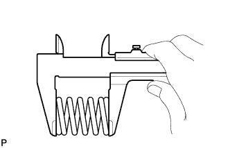
Using a vernier caliper, measure the free length of the compression spring.
- Free length:
- 43 mm (1.69 in.)
Connect the center exhaust pipe to the 3 exhaust pipe supports.
Set 2 new gaskets to the front No. 1 and No. 2 exhaust pipes.
Install the center exhaust pipe with the 4 bolts and 2 compression springs.
- Torque:
- for center exhaust pipe and front No. 1 exhaust pipe:
- 49 N*m{ 496 kgf*cm , 36 ft.*lbf }
- for center exhaust pipe and front No. 2 exhaust pipe:
- 48 N*m{ 489 kgf*cm , 35 ft.*lbf }
| 8. INSTALL TAILPIPE ASSEMBLY |
Connect the tailpipe to the 2 exhaust pipe supports.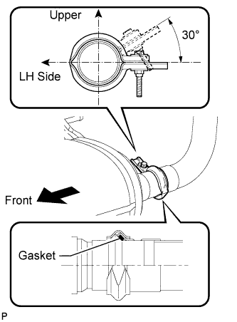
Set a new gasket to the center exhaust pipe.
Connect the tailpipe to the center exhaust pipe with a new clamp.
- HINT:
- Install the clamp within the angle range shown in the illustration.
Tighten the bolt.
- Torque:
- 32 N*m{ 326 kgf*cm , 24 ft.*lbf }
| 9. INSPECT FOR EXHAUST GAS LEAK |
| 10. INSTALL NO. 2 ENGINE UNDER COVER |
Install the under cover the with the 6 bolts.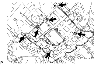
- Torque:
- 29 N*m{ 296 kgf*cm , 21 ft.*lbf }
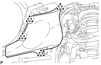
| 11. INSTALL FRONT FENDER APRON SEAL REAR LH |
Install the fender apron seal with the 4 clips.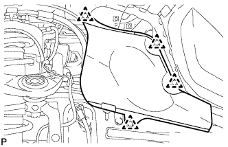
| 12. INSTALL FRONT FENDER APRON SEAL REAR RH |
Install the fender apron seal with the 4 clips.