REMOVAL
Removal / installation · Vehicles built from Jan 2012
- CAUTION:
- Wear protective gloves and protective glasses when removing the exhaust pipe.
- The exhaust pipe is extremely hot immediately after the engine has stopped.
- Confirm that the exhaust pipe has cooled down before removing it.
| 1.
REMOVE AIR FUEL RATIO SENSOR |
 |
(Click here)
| 2.
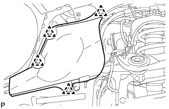
REMOVE FRONT FENDER APRON SEAL REAR RH
|
|
- Remove the 4 clips and front fender apron seal rear RH.
| 3.
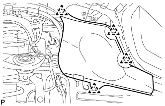
REMOVE FRONT FENDER APRON SEAL REAR LH
|
|
- Remove the 4 clips and front fender apron seal rear LH.
| 4.
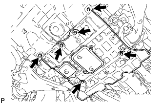
REMOVE NO. 2 ENGINE UNDER COVER |
|
- Remove the 6 bolts and No. 2 engine under cover.
| 5.
REMOVE TAILPIPE ASSEMBLY |
|
Remove the bolt, clamp and gasket.
Disconnect the tailpipe from the 2 exhaust pipe supports.
| 6.
REMOVE CENTER EXHAUST PIPE ASSEMBLY |
|
Remove the 4 bolts and 2 compression springs.
Disconnect the center exhaust pipe from the 3 exhaust pipe supports.
Remove the gasket from the No. 5 exhaust pipe and front exhaust pipe.
| 7.
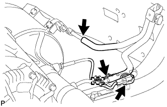
REMOVE FRONT EXHAUST PIPE ASSEMBLY |
|
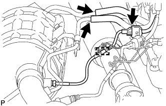
- Disconnect the 2 air hoses.
Disconnect the exhaust gas temperature sensor connector and detach the clamp.
Remove the 3 nuts and front exhaust pipe.
Remove the gasket.
| 8.
REMOVE NO. 5 EXHAUST PIPE ASSEMBLY |
|
Remove the 2 nuts and No. 5 exhaust pipe.
Remove the gasket.
| 9.
REMOVE FRONT NO. 2 EXHAUST PIPE ASSEMBLY |
|
- Disconnect the 2 air hoses.
Disconnect the exhaust gas temperature sensor connector and detach the clamp.
Remove the 3 nuts and front No. 2 exhaust pipe.
Remove the gasket.
| 10.
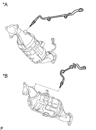
REMOVE NO. 4 EXHAUST GAS TEMPERATURE SENSOR
|
|
- NOTICE:
- If the sensor is dropped, replace it with a new one.
Text in Illustration
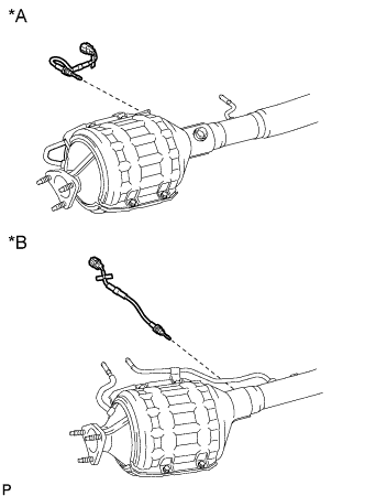
*A
|
for Bank 1
|
*B
|
for Bank 2
|
Using a 14 mm union nut wrench, remove the 2 No. 4 exhaust gas temperature sensors.
| 11.
REMOVE MONOLITHIC CONVERTER ASSEMBLY RH |
|
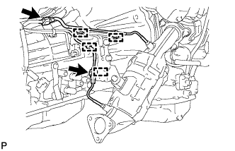
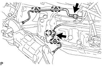
- Disconnect the 2 exhaust gas temperature sensor connectors and detach the 4 clamps.
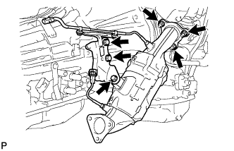
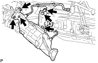
- Remove the 3 bolts and manifold stay.
Remove the 3 nuts and monolithic converter RH.
Remove the gasket from the turbocharger.
| 12.
REMOVE FRONT PROPELLER SHAFT ASSEMBLY |
|
(Click here)
| 13.
REMOVE MONOLITHIC CONVERTER ASSEMBLY LH |
|
- Disconnect the 2 exhaust gas temperature sensor connectors and detach the 4 clamps.
- Remove the 3 bolts and No. 2 manifold stay.
Remove the 3 nuts and monolithic converter LH.
Remove the gasket from the turbocharger.
| 14.
REMOVE NO. 3 EXHAUST GAS TEMPERATURE SENSOR
|
|
- NOTICE:
- If the sensor is dropped, replace it with a new one.
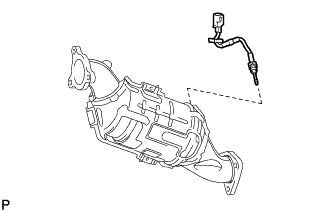
Using a 14 mm union nut wrench, remove the No. 3 exhaust gas temperature sensor.
| 15.
REMOVE NO. 2 EXHAUST GAS TEMPERATURE SENSOR
|
|
- NOTICE:
- If the sensor is dropped, replace it with a new one.
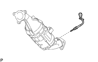
Using a 14 mm union nut wrench, remove the No. 2 exhaust gas temperature sensor.
| 16.
REMOVE EXHAUST GAS TEMPERATURE SENSOR
|
|
- NOTICE:
- If the sensor is dropped, replace it with a new one.
Text in Illustration
*A
|
for Bank 1
|
*B
|
for Bank 2
|
Using a 14 mm union nut wrench, remove the 2 exhaust gas temperature sensors.