REMOVAL
Removal / installation · Vehicles built Sep 2011 – Dec 2011
Versions by build date: Sep 2011 – Dec 2011 from Jan 2012
- HINT:
- Use the same procedures for the LHD vehicle and RHD vehicle.
- The procedures listed below are for the LHD vehicle.
- Use the same procedures for the LHD vehicle and RHD vehicle.
| 1. DISCONNECT CABLE FROM NEGATIVE BATTERY TERMINAL |

- CAUTION:
- Wait at least 90 seconds after disconnecting the cable from the negative (-) battery terminal to disable the SRS system.
- NOTICE:
- When disconnecting the cable, some systems need to be initialized after the cable is reconnected (Click here).
| 2. REMOVE NO. 1 SPEAKER OPENING COVER ASSEMBLY |
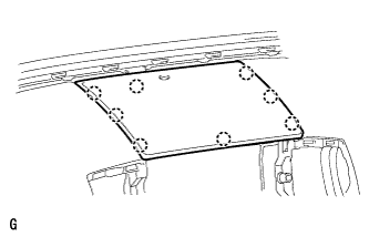  |
Detach the 8 claws and remove the opening cover.
| 3. REMOVE NO. 3 INSTRUMENT PANEL REGISTER ASSEMBLY |
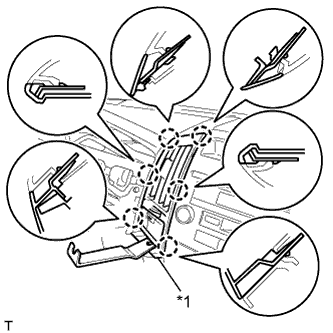 |
Place protective tape as shown in the illustration.
Text in Illustration *1
Protective Tape
Using a moulding remover, detach the 6 claws.
Disconnect the connector and remove the No. 3 instrument panel register.
| 4. REMOVE NO. 4 INSTRUMENT PANEL REGISTER ASSEMBLY |
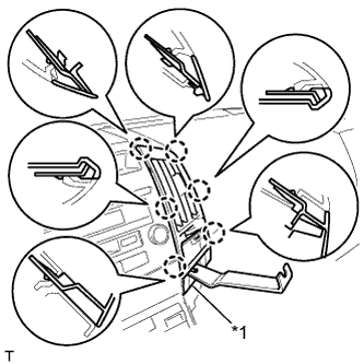 |
Place protective tape as shown in the illustration.
Text in Illustration *1
Protective Tape
Using a moulding remover, detach the 6 claws.
Disconnect the connector and remove the No. 4 instrument panel register.
| 5. REMOVE RADIO RECEIVER ASSEMBLY WITH BRACKET |
w/ Cassette Tape Player:
Remove the radio receiver assembly with bracket (Click here).
w/o Multi-dsplay:
Remove the radio receiver assembly with bracket (Click here).
| 6. REMOVE NO. 1 CENTER INSTRUMENT CLUSTER FINISH PANEL |
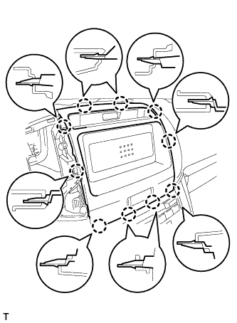 |
Detach the 10 claws.
Disconnect the connector and remove the No. 1 center instrument cluster finish panel.
| 7. REMOVE NO. 2 INSTRUMENT PANEL FINISH PANEL CUSHION |
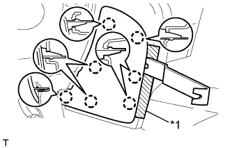 |
Put protective tape around the No. 2 instrument panel finish panel cushion.
Text in Illustration *1
Protective Tape
Using a moulding remover, detach the 7 claws and remove the No. 2 instrument panel finish panel cushion.
| 8. REMOVE LOWER INSTRUMENT PANEL PAD SUB-ASSEMBLY LH |
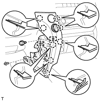 |
Remove the clip and screw.
Detach the 8 claws.
Disconnect the connectors, detach the 2 clamps and remove the lower instrument panel pad sub-assembly.
| 9. REMOVE NO. 1 INSTRUMENT PANEL FINISH PANEL CUSHION |
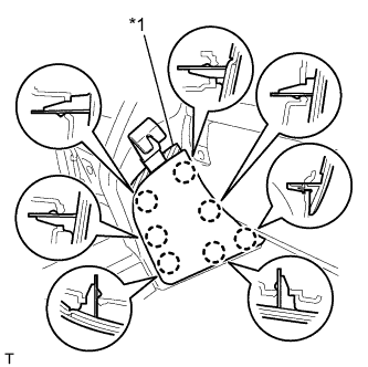 |
Put protective tape around the No. 1 instrument panel finish panel cushion.
Text in Illustration *1
Protective Tape
Using a moulding remover, detach the 7 claws and remove the No. 1 instrument panel finish panel cushion.
| 10. REMOVE LOWER INSTRUMENT PANEL PAD SUB-ASSEMBLY RH |
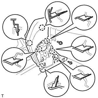 |
Remove the clip and screw.
Detach the 7 claws and remove the lower instrument panel pad sub-assembly.
| 11. REMOVE LOWER CENTER INSTRUMENT CLUSTER FINISH PANEL SUB-ASSEMBLY |
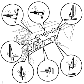 |
Detach the 7 claws.
Disconnect the connectors and remove the lower center instrument cluster finish panel sub-assembly.
| 12. REMOVE AIR CONDITIONING CONTROL ASSEMBLY |
Pull the radio receiver to detach the 5 claws on the backside of the radio receiver.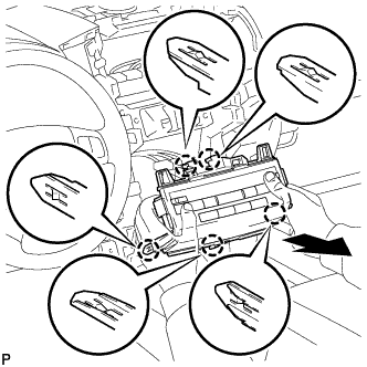
Disconnect the connectors and remove the radio receiver.