DISASSEMBLY
Removal / installation · Vehicles built Sep 2011 – Dec 2011
Versions by build date: Sep 2011 – Dec 2011 from Jan 2012
| 1.
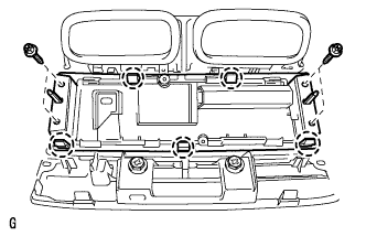
REMOVE NO. 2 AIR CONDITIONING CONTROL ASSEMBLY (w/ Rear Air Conditioning System)
|
 |
Remove the 4 screws.
Detach the 5 claws and remove the air conditioning control.
| 2.
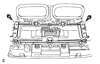
REMOVE AIR CONDITIONING CONTROL ASSEMBLY (w/ Rear Cooler)
|
|
Remove the 4 screws.
Detach the 5 claws and remove the air conditioning control.
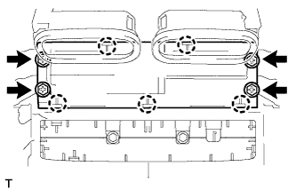
| 3.
REMOVE REAR COOLER SWITCH HOLE COVER (w/o Rear Cooler) |
|
- Remove the 4 screws.
Detach the 5 claws and remove the hole cover.
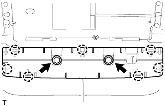
| 4.
REMOVE INSTRUMENT PANEL HOLE COVER |
|
- Remove the 2 screws.
Detach the 7 claws and remove the hole cover.
| 5.
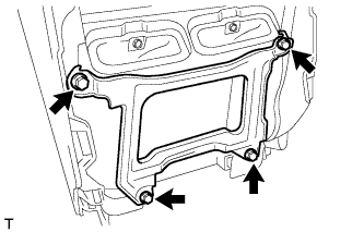
REMOVE REAR CONSOLE BOX MOUNTING BRACKET |
|
- Remove the 4 screws and bracket.
| 6.
REMOVE CONSOLE COMPARTMENT DOOR SUB-ASSEMBLY |
|
- Remove the 6 screws and door.
| 7.
REMOVE CONSOLE COMPARTMENT DOOR LOCK SUB-ASSEMBLY |
|
- Remove the 12 screws, lower box and door lock.
| 8.
REMOVE CONSOLE COMPARTMENT DOOR HINGE SUB-ASSEMBLY |
|
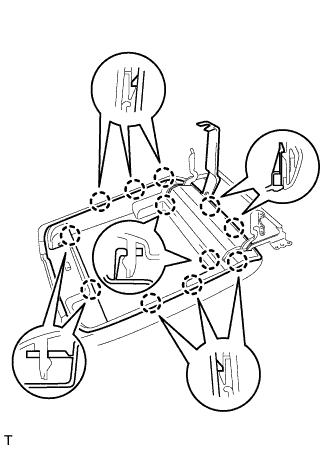
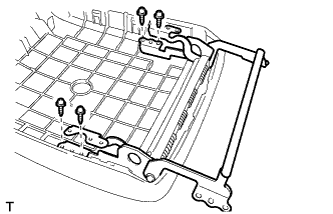
- Using a moulding remover, detach the 12 claws and remove the inner door.
- Remove the 4 screws and door hinge.
| 9.
REMOVE CONSOLE COMPARTMENT DOOR LOCK |
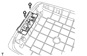
|
- Remove the 2 screws and door lock.
| 10.
REMOVE COOLING BOX ASSEMBLY |
|
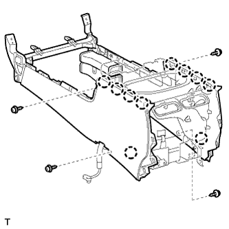
- Remove the 4 screws.
Detach the 10 claws and remove the cooling box.
| 11.
REMOVE AIR CONDITIONING AMPLIFIER ASSEMBLY |
|
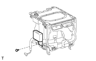
- Disconnect the connector.
Remove the screw and amplifier.
| 12.
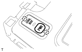
REMOVE COOLER CONTROL SWITCH SUB-ASSEMBLY |
|
- Detach the 2 claws.
Disconnect the connector and remove the switch.
| 13.
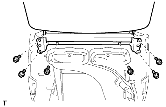
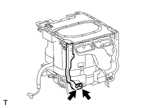
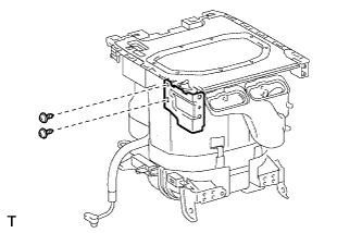
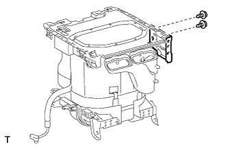
REMOVE NO. 2 COOLING BOX BRACKET |
|
- Remove the 2 screws and mounting bracket.
- Remove the 2 screws and bracket.
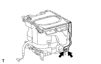
| 14.
REMOVE COOLING BOX BRACKET |
|
- Remove the 2 screws and mounting bracket.
- Remove the 2 screws and bracket.
| 15.
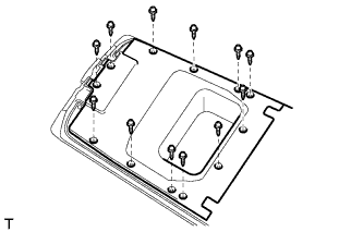
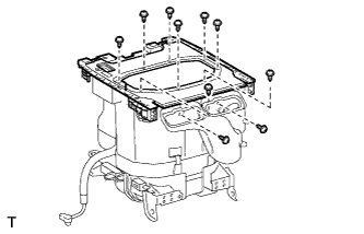
REMOVE COOLING BOX BASE |
|
- Remove the 10 screws and cooling box base.
| 16.
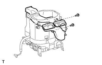
REMOVE COOLING UNIT CASE SUB-ASSEMBLY |
|
- Remove the 2 screws and air duct from the case.
| 17.
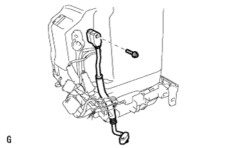
REMOVE LIQUID HOSE |
|
- Remove the bolt and liquid hose.
Remove the O-ring from the liquid hose.
| 18.
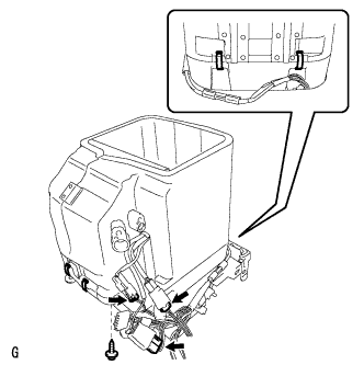
REMOVE LOWER COOLING UNIT CASE SUB-ASSEMBLY |
|
Remove the screw.
Disconnect the 3 connectors.
Remove the 4 holding springs and lower cooling unit case.
| 19.
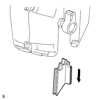
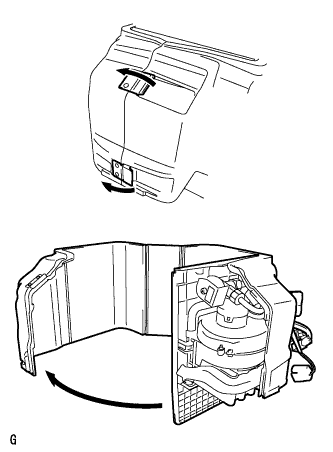
REMOVE UPPER COOLING UNIT CASE |
|
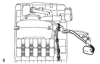
- Remove the cooling unit case.
- Detach the 2 hooks and open the case, as shown in the illustration.
| 20.
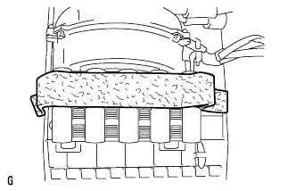
REMOVE NO. 3 COOLER THERMISTOR |
|
- Remove the cool box insulator.
- Remove the thermistor.
| 21.
REMOVE NO. 1 COOLER BLOWER MOTOR SUB-ASSEMBLY |
|
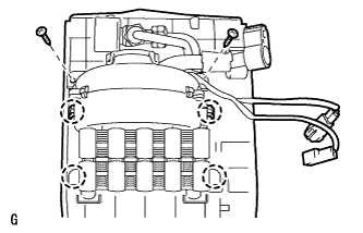
- Remove the 2 screws.
Detach the 4 claws and remove the blower motor.
| 22.
REMOVE NO. 2 COOLER EVAPORATOR SUB-ASSEMBLY |
|
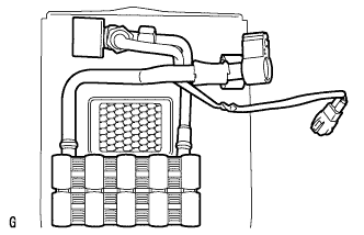
- Remove the evaporator.