BODY DIMENSIONS FRAME TWO-DIMENSIONAL DISTANCE
Upper Face
- HINT:
-
For symbols, capital letters indicate right side of vehicle, small letters indicate left side of vehicle (seen from rear).
| Symbol | Name | Hole Diameter
mm (in.) |
|---|---|---|
| A, a | Front bamper extension No. 2 installation bolt | M10 (0.39) |
| B, b | No. 1 body mounting hole | φ26 (1.02) |
| C, c | Front spring support hole | φ12.2 (0.480) |
| D, d | No. 2 body mounting hole | φ43 (1.69) |
| E, e | Side rail inner channel standard hole | 16X16 (0.63X0.63) |
| F, f | No. 3 body mounting hole | φ43 (1.69) |
| G, g | No. 4 body mounting hole | φ43 (1.69) |
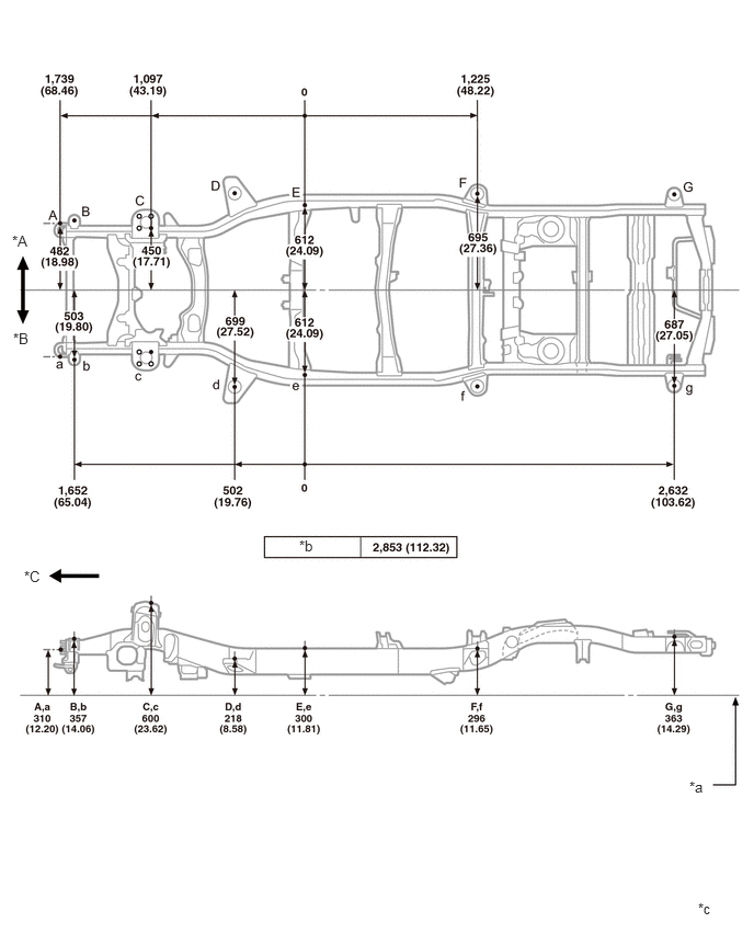
| *A | RH | *B | LH |
| *C | Front | - | - |
| *a | Imaginary Datum Line | *b | Wheel base |
| *c | mm
(in.) |
- | - |
Lower Face
- HINT:
-
For symbols, capital letters indicate right side of vehicle, small letters indicate left side of vehicle (seen from rear).
| Symbol | Name | Hole Diameter
mm (in.) |
|---|---|---|
| A, a | Front bamper extension No. 2 installation bolt | M10 (0.39) |
| B, b | Front stabilizer bracket installation nut | M12 (0.47) |
| C, c | Suspension lower arm installation hole - rear | 42 X24 (1.65X0.94) |
| D, d | Suspension lower arm installation hole - front | 36.5X18.5 (1.437X0.728) |
| E, e | Side rail inner channel standard hole | 16X16 (0.63X0.63) |
| F, f | Lower control arm installation hole - inner | φ16.5 (0.650) |
| G, g | Upper control arm installation hole - inner | φ14.5 (0.571) |
| H, h | Rear shock absorber installation hole | φ29.5 (1.161) |
| I | Lateral control rod installation hole - front | φ15 (0.59) |
| J, j | Transport hook installation nut | M12 (0.47) |
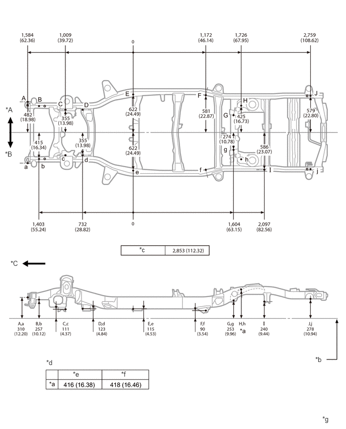
| *A | RH | *B | LH |
| *C | Front | - | - |
| *b | Imaginary Datum Line | *c | Wheel base |
| *d | Vehicle Dimensions | *e | Heavy Duty |
| *f | Light Duty | *g | mm
(in.) |
Upper Face (w/ Kinetic Dynamic Suspension System)
- HINT:
-
For symbols, capital letters indicate right side of vehicle, small letters indicate left side of vehicle (seen from rear).
| Symbol | Name | Hole Diameter
mm (in.) |
|---|---|---|
| A, a | Front bamper extension No. 2 installation bolt | M10 (0.39) |
| B, b | No. 1 body mounting hole | φ26 (1.02) |
| C, c | Front spring support hole | φ12.2 (0.480) |
| D, d | No. 2 body mounting hole | φ43 (1.69) |
| E, e | Side rail inner channel standard hole | 16X16 (0.63X0.63) |
| F, f | No. 3 body mounting hole | φ43 (1.69) |
| G, g | No. 4 body mounting hole | φ43 (1.69) |
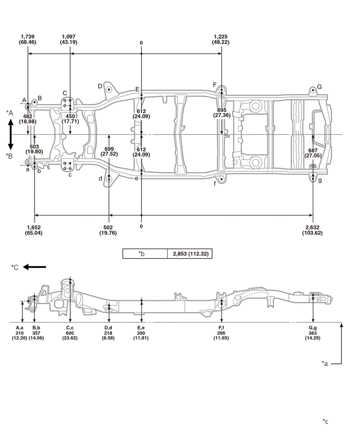
| *A | RH | *B | LH |
| *C | Front | - | - |
| *a | Imaginary Datum Line | *b | Wheel base |
| *c | mm
(in.) |
- | - |
Lower Face (w/ Kinetic Dynamic Suspension System)
- HINT:
-
For symbols, capital letters indicate right side of vehicle, small letters indicate left side of vehicle (seen from rear).
| Symbol | Name | Hole Diameter
mm (in.) |
|---|---|---|
| A, a | Front bamper extension No. 2 installation bolt | M10 (0.39) |
| B, b | Front stabilizer bracket installation nut | M12 (0.47) |
| C, c | Kinetic Dynamic Suspension System bracket installation hole | φ18.5 (0.728) |
| D, d | Suspension lower arm installation hole - rear | 42X24(1.65X0.94) |
| E, e | Suspension lower arm installation hole - front | 36.5X18.5 (1.437X0.728) |
| F, f | Side rail inner channel standard hole | 16X16(0.63X0.63) |
| G, g | Lower control arm installation hole - inner | φ16.5 (0.650) |
| H, h | Upper control arm installation hole - inner | φ14.5 (0.571) |
| I, i | Rear shock absorber installation hole | φ29.5 (1.161) |
| J | Lateral control rod installation hole - front | φ15 (0.59) |
| K, k | Transport hook installation nut | M12 (0.47) |
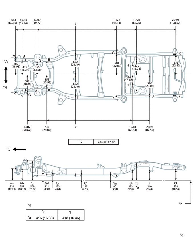
| *A | RH | *B | LH |
| *C | Front | - | - |
| *b | Imaginary Datum Line | *c | Wheel base |
| *d | Vehicle Dimensions | *e | Heavy Duty |
| *f | Light Duty | *g | mm
(in.) |
Upper Face (w/ Winch)
- HINT:
-
For symbols, capital letters indicate right side of vehicle, small letters indicate left side of vehicle (seen from rear).
| Symbol | Name | Hole Diameter
mm (in.) |
|---|---|---|
| A, a | Winch bracket installation nut | M12 (0.47) |
| B, b | No. 1 body mounting hole | φ26 (1.02) |
| C, c | Front spring support hole | φ12.2 (0.480) |
| D, d | No. 2 body mounting hole | φ43 (1.69) |
| E, e | Side rail inner channel standard hole | 16X16 (0.63X0.63) |
| F, f | No. 3 body mounting hole | φ43 (1.69) |
| G, g | No. 4 body mounting hole | φ43 (1.69) |
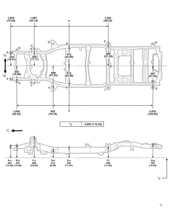
| *A | RH | *B | LH |
| *C | Front | - | - |
| *a | Imaginary Datum Line | *b | Wheel base |
| *c | mm
(in.) |
- | - |
Lower Face (w/ Winch)
- HINT:
-
For symbols, capital letters indicate right side of vehicle, small letters indicate left side of vehicle (seen from rear).
| Symbol | Name | Hole Diameter
mm (in.) |
|---|---|---|
| A, a | Winch bracket installation nut | M12 (0.47) |
| B, b | Front stabilizer bracket installation nut | M12 (0.47) |
| C, c | Suspension lower arm installation hole - rear | 42X24 (1.65X0.94) |
| D, d | Suspension lower arm installation hole - front | 36.5X18.5 (1.437X0.728) |
| E, e | Side rail inner channel standard hole | 16X16 (0.63X0.63) |
| F, f | Lower control arm installation hole - inner | φ16.5 (0.650) |
| G, g | Upper control arm installation hole - inner | φ14.5 (0.571) |
| H, h | Rear shock absorber installation hole | φ29.5 (1.161) |
| I | Lateral control rod installation hole - front | φ15 (0.59) |
| J, j | Transport hook installation nut | M12 (0.47) |
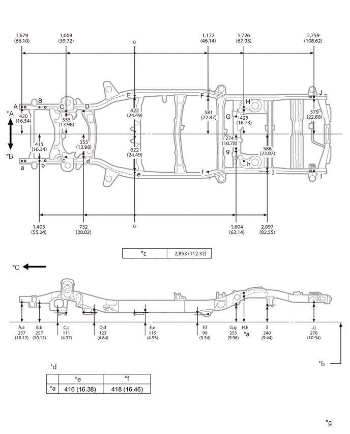
| *A | RH | *B | LH |
| *C | Front | - | - |
| *b | Imaginary Datum Line | *c | Wheel base |
| *d | Vehicle Dimensions | *e | Heavy Duty |
| *f | Light Duty | *g | mm
(in.) |