BODY PANEL FIT STANDARD / ADJUSTMENT METHOD ADJUSTMENT
Refer to the TOYOTA Repair Manual for adjustment method.
- HINT:
-
Vehicle Exterior > DOOR / HATCH
INSPECT HOOD
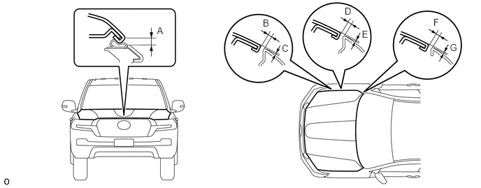
Check that the clearance measurements of areas A to C are within the standard range.
- Standard Measurement:
Area Specified Condition Area Specified Condition A (Reference) 7.9 mm (0.311 in.) B 2.0 to 5.0 mm (0.0787 to 0.197 in.) C -1.5 to 1.5 mm (-0.0591 to 0.0591 in.) D 2.0 to 5.0 mm (0.0787 to 0.197 in.) E -1.5 to 1.5 mm (-0.0591 to 0.0591 in.) F 2.0 to 5.0 mm (0.0787 to 0.197 in.) G -1.5 to 1.5 mm (-0.0591 to 0.0591 in.) - -
- HINT:
-
Centering bolts are used to mount the hood hinge and hood lock. The hood and hood lock cannot be adjusted with the centering bolts on. Substitute the centering bolts with standard bolts (with washers) when making adjustments.
INSPECT FRONT DOOR
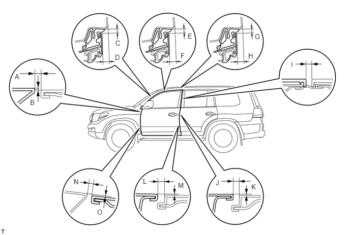
Check that the clearance measurements of areas A to O are within the standard range.
- Standard Measurement:
Area Measurement Area Measurement A 2.2 to 5.2 mm (0.087 to 0.205 in.) I 3.5 to 6.5 mm (0.138 to 0.256 in.) B -1.5 to 1.5 mm (-0.0591 to 0.0591 in.) J 2.5 to 5.5 mm (0.0984 to 0.217 in.) C 3.3 to 6.3 mm (0.130 to 0.248 in.) K -1.5 to 1.5 mm (-0.0591 to 0.0591 in.) D 6.0 to 9.0 mm (0.236 to 0.354 in.) L 2.5 to 5.5 mm (0.0984 to 0.217 in.) E 3.4 to 6.4 mm (0.134 to 0.252 in.) M -1.5 to 1.5 mm (-0.0591 to 0.0591 in.) F 6.9 to 9.9 mm (0.272 to 0.390 in.) N 2.2 to 5.2 mm (0.0866 to 0.205 in.) G 3.4 to 6.4 mm (0.134 to 0.252 in.) O -1.5 to 1.5 mm (-0.0591 to 0.0591 in.) H 6.6 to 9.6 mm (0.260 to 0.378 in.) - -
- HINT:
- ·
Before adjusting the door position for vehicles equipped with side airbags and curtain shield airbags, be sure to disconnect the cable from the negative (-) battery terminal.
·Use the same procedures for the RH side and LH side.
·The procedures listed below are for the LH side.
·Centering bolts are used to mount the door hinge to the vehicle body and door. The door cannot be adjusted with the centering bolts on. Substitute the centering bolts with standard bolts (with washers) when making adjustments.
INSPECT REAR DOOR
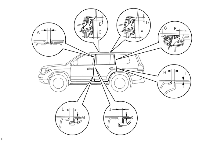
Check that the clearance measurements of areas A to M are within the standard range.
- Standard Measurement:
Area Specified Condition Area Specified Condition A 3.5 to 6.5 mm (0.139 to 0.256 in.) H 2.2 to 5.2 mm (0.0866 to 0.205 in.) B 3.4 to 6.4 mm (0.134 to 0.252 in.) I -1.5 to 1.5 mm (-0.0591 to 0.0591 in.) C 6.5 to 9.5 mm (0.256 to 0.374 in.) J 2.5 to 5.5 mm (0.0984 to 0.217 in.) D 3.4 to 6.4 mm (0.134 to 0.252 in.) K -1.5 to 1.5 mm (-0.0591 to 0.0591 in.) E 5.6 to 8.6 mm (0.221 to 0.339 in.) L 2.5 to 5.5 mm (0.0984 to 0.217 in.) F 5.0 to 8.0 mm (0.197 to 0.315 in.) M -1.5 to 1.5 mm (-0.0591 to 0.0591 in.) G 1.2 to 4.2 mm (0.0472 to 0.165 in.) - -
- HINT:
- ·
Before adjusting the door position for vehicles equipped with side airbags and curtain shield airbags, be sure to disconnect the cable from the negative (-) battery terminal.
·Use the same procedures for the RH side and LH side.
·The procedures listed below are for the LH side.
·Centering bolts are used to mount the door hinge to the vehicle body and door. The door cannot be adjusted with the centering bolts on. Substitute the centering bolts with standard bolts (with washers) when making adjustments.
INSPECT TAIL GATE PANEL (w/o Tire Carrier)
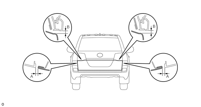
Check that the clearance measurements of areas A to B are within the standard range.
- Standard:
Area Specified Condition Area Specified Condition A 3.35 to 6.35mm (0.132 to 0.250 in.) B 4.05 to 7.05mm (0.159 to 0.278 in.)
INSPECT TAIL GATE PANEL (w/ Tire Carrier)
Check that the clearance measurements of areas A to B are within the standard range.
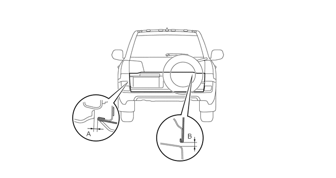
- Standard:
Area Specified Condition Area Specified Condition A 3.35 to 6.35mm (0.132 to 0.250 in.) B 3.35 to 6.35mm (0.132 to 0.250 in.)
INSPECT BACK DOOR PANEL
Check that the clearance measurements of areas A to G are within the standard range.
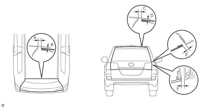
- Standard Measurement:
Area Specified Condition Area Specified Condition A 4.7 to 7.7 mm (0.185 to 0.303 in.) D 1.5 to 4.5mm (0.059 to 0.177 in.) B 1.5 to 4.5mm (0.059 to 0.177 in.) E 3.2 to 6.2mm (0.126 to 0.244 in.) C 4.8 to 7.8mm (0.189 to 0.307 in.) F 3.5 to 6.5mm (0.138 to 0.256 in.)
INSPECT BACK DOOR PANEL RH (for RH Side)
Check that the clearance measurements of areas A to P are within the standard ranges.
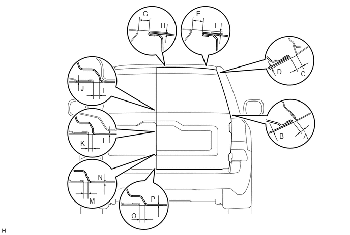
- Standard:
Area Specified Condition Area Specified Condition A 4.6 to 8.6 mm (0.181 to 0.339 in.) B -2 to 2 mm (-0.0787 to 0.0787 in.) C 6.0 to 10.0 mm (0.236 to 0.394 in.) D -0.9 to 3.1 mm (-0.0354 to 0.122 in.) E 11.3 to 14.3 mm (0.445 to 0.563 in.) F 0.5 to 3.5 mm (0.0197 to 0.138 in.) G 11.3 to 14.3 mm (0.445 to 0.563 in.) H 0 to 3.0 mm (0 to 0.118 in.) I 3.5 to 7.5 mm (0.138 to 0.295 in.) J -2 to 2 mm (-0.0787 to 0.0787 in.) K 3.5 to 7.5 mm (0.138 to 0.295 in.) L -2 to 2 mm (-0.0787 to 0.0787 in.) M 3.5 to 7.5 mm (0.138 to 0.295 in.) N -1.8 to 2.2 mm (-0.0709 to 0.0866 in.) O 3.5 to 7.5 mm (0.138 to 0.295 in.) P -2 to 2 mm (-0.0787 to 0.0787 in.)
- NOTICE:
-
Centering bolts are used to mount the door hinge to the vehicle body and door. The door cannot be adjusted with the centering bolts on. Substitute the centering bolts for standard bolts when making adjustments.
INSPECT BACK DOOR PANEL LH (for LH Side)
Check that the clearance measurements of areas A to P are within the standard ranges.
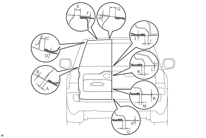
- Standard:
Area Specified Condition Area Specified Condition A 4.6 to 8.6 mm (0.181 to 0.339 in.) B -2 to 2 mm (-0.0787 to 0.0787 in.) C 6.0 to 10.0 mm (0.236 to 0.394 in.) D -0.9 to 3.1 mm (-0.0354 to 0.122 in.) E 11.3 to 14.3 mm (0.445 to 0.563 in.) F 0.3 to 3.3 mm (0.0118 to 0.130 in.) G 11.3 to 14.3 mm (0.445 to 0.563 in.) H 0 to 3.0 mm (0 to 0.118 in.) I 3.5 to 7.5 mm (0.138 to 0.295 in.) J -2 to 2 mm (-0.0787 to 0.0787 in.) K 3.5 to 7.5 mm (0.138 to 0.295 in.) L -2 to 2 mm (-0.0787 to 0.0787 in.) M 3.5 to 7.5 mm (0.138 to 0.295 in.) N -1.8 to 2.2 mm (-0.0709 to 0.0866 in.) O 3.5 to 7.5 mm (0.138 to 0.295 in.) P -2 to 2 mm (-0.0787 to 0.0787 in.)