Home › General › ENGINE › 1UR-FE ENGINE
NM2660E _V1 General _054359 ENGINE _0265192 1UR-FE ENGINE UN GENERAL/CONTROL/DETAILS F

ENGINE  1UR-FE ENGINE  GENERAL/CONTROL/DETAILS  LUBRICATION SYSTEM  


General


a.

The lubrication circuit is fully pressurized and oil passes through an oil filter.


b.

A cycloid rotor type oil pump is used.


c.

An oil filter with a replaceable element is used.


d.

A water-cooled type oil cooler is used.
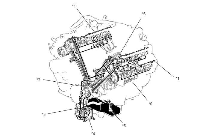
W133011C01
3.292,1.115 2.688,0.323 true 6.042,2.667 5.365,2.115 true 2.938,3.01 1.5,2.76 true 2.656,3.76 1.656,3.948 true 3.219,4.51 3.083,4.104 true 4.26,4.26 3.865,3.844 true 5.115,3.458 4.229,2.385 true 4.917,0.615 4.021,2.125 true 2.51,0.125 2.823,0.281 0.313,0.156 10 false *1 1.271,2.688 1.583,2.844 0.313,0.156 10 false *2 1.458,3.885 1.771,4.042 0.313,0.156 10 false *3 3.177,4.552 3.49,4.708 0.313,0.156 10 false *4 4.25,4.281 4.563,4.438 0.313,0.156 10 false *5 6.115,2.635 6.427,2.792 0.313,0.156 10 false *1 5.167,3.521 5.479,3.719 0.313,0.198 10 false *6 4.938,0.396 5.25,0.594 0.313,0.198 10 false *6
*1 Oil Delivery Pipe (Cylinder Head Cover) *2 Oil Pump
*3 Oil Filter *4 Oil Cooler
*5 Oil Strainer *6 Camshaft Timing Oil Control Valve


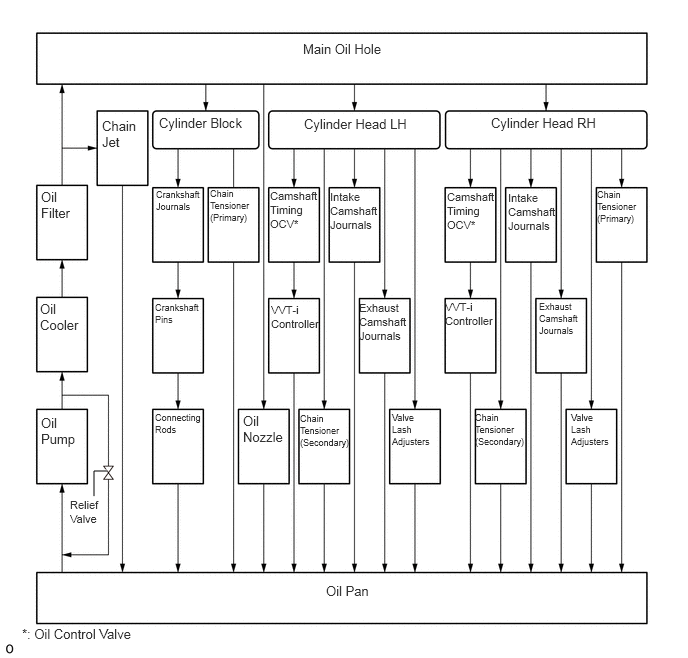
Oil Circuit
W128388E11
0.979,5.167 0.979,4.906 0.979,4.906 1.115,4.906 true 3.156,0.427 4.26,0.781 1.104,0.354 10 false Main Oil Hole 1.063,1.229 1.469,1.833 0.406,0.604 10 false Chain Jet 1.656,1.198 2.635,1.5 0.979,0.302 10 false Cylinder Block 3.167,1.208 4.354,1.5 1.188,0.292 10 false Cylinder Head LH 5.115,1.198 6.365,1.469 1.25,0.271 10 false Cylinder Head RH 0.427,1.969 0.833,2.573 0.406,0.604 10 false Oil Filter 1.625,1.969 2.094,2.688 0.469,0.719 7 false Crankshaft Journals 2.188,1.958 2.708,2.708 0.521,0.75 7 false Chain Tensioner (Primary) 2.813,1.969 3.323,2.688 0.51,0.719 8 false Camshaft Timing OCV* 3.438,1.979 3.938,2.698 0.5,0.719 8 false Intake Camshaft Journals 4.656,1.979 5.146,2.719 0.49,0.74 8 false Camshaft Timing OCV* 5.292,1.99 5.771,2.677 0.479,0.688 8 false Intake Camshaft Journals 6.219,1.969 6.708,2.708 0.49,0.74 7 false Chain Tensioner (Primary) 5.615,3.135 6.094,3.885 0.479,0.75 7 false Exhaust Camshaft Journals 4.635,3.125 5.167,3.875 0.531,0.75 8 false VVT-i Controller 3.74,3.135 4.25,3.875 0.51,0.74 8 false Exhaust Camshaft Journals 2.823,3.156 3.323,3.844 0.5,0.688 8 false VVT-i Controller 1.615,3.146 2.083,3.813 0.469,0.667 7 false Crankshaft Pins 0.417,3.135 0.875,3.823 0.458,0.688 10 false Oil Cooler 1.615,4.292 2.135,5.021 0.521,0.729 7 false Connecting Rods 2.531,4.302 2.938,4.906 0.406,0.604 10 false Oil Nozzle 3.125,4.302 3.667,5.021 0.542,0.719 7 false Chain Tensioner (Secondary) 4.948,4.292 5.51,5.031 0.563,0.74 7 false Chain Tensioner (Secondary) 0.229,6.521 1.5,6.813 1.271,0.292 10 false *: Oil Control Valve 0.427,4.323 0.833,4.927 0.406,0.604 10 false Oil Pump 0.729,5.188 1.104,5.75 0.375,0.563 8 false Relief Valve 3.396,6.073 3.969,6.354 0.573,0.281 10 false Oil Pan 4.083,4.292 4.5,5.01 0.417,0.719 7 false Valve Lash Adjusters 5.948,4.292 6.365,5.01 0.417,0.719 7 false Valve Lash Adjusters


Oil Pump


a.

A compact cycloid rotor type oil pump directly driven by the crankshaft is used.


b.

This oil pump uses an internal relief method which circulates relief oil to the suction passage in the oil pump. This aims to minimize oil level change in the oil pan, reduce friction, and reduce the air mixing rate in the oil.
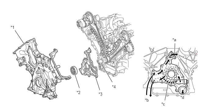
W131961C01
2.708,3.021 2.552,2.542 true 3.406,3.094 3.25,2.615 true 3.833,2.823 3.438,2.146 true 0.823,1.51 0.51,1.042 true 5.958,1.844 5.969,1.49 true 5.625,3.448 5.75,2.823 true 0.365,0.854 0.677,1.01 0.313,0.156 10 false *1 2.615,3.094 2.927,3.25 0.313,0.156 10 false *2 3.365,3.146 3.677,3.302 0.313,0.156 10 false *3 3.823,2.896 4.135,3.052 0.313,0.156 10 false *4 5.885,1.281 6.198,1.438 0.313,0.156 10 false *a 4.948,3.354 5.26,3.51 0.313,0.156 10 false *b 5.51,3.49 5.823,3.646 0.313,0.156 10 false *c 6.156,3.26 6.469,3.417 0.313,0.156 10 true *d
*1 Timing Chain Cover *2 Oil Pump Rotor (Cycloid Rotor)
*3 Oil Pump Cover *4 Crankshaft
*a To Cylinder Block *b Oil Filter
*c Relief Oil *d From Oil Strainer


Oil Nozzle


a.

4 oil nozzle sub-assemblies for cooling and lubricating the pistons are provided in the cylinder block in the center of the right and left banks.


b.

These oil nozzle sub-assemblies contain a check valve to prevent oil from being fed when the oil pressure is low. This prevents the overall oil pressure in the engine from dropping.
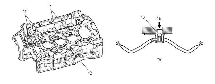
W131962C01
1.073,1.438 0.833,0.479 0.833,0.479 1.5,1.333 true 1.917,1.219 1.688,0.302 1.688,0.302 2.344,1.115 true 2.938,2.333 2.656,2 true 5.281,1.135 4.865,0.667 true 0.76,0.292 1.073,0.448 0.313,0.156 10 false *1 2.938,2.354 3.25,2.51 0.313,0.156 10 false *2 4.698,0.49 5.01,0.646 0.313,0.156 10 false *3 5.24,1.906 5.552,2.063 0.313,0.156 10 false *b 5.229,0.521 5.542,0.677 0.313,0.156 10 false *a 1.604,0.125 1.917,0.281 0.313,0.156 10 false *1
*1 Oil Nozzle Sub-assembly *2 Cylinder Block
*3 Check Valve - -
*a Oil *b Oil Nozzle Sub-assembly Cross Section


Oil Filter


a.

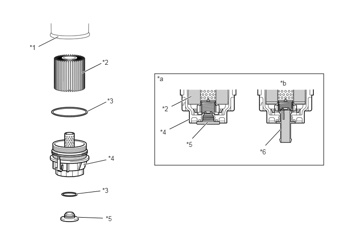
An oil filter with a replaceable element is used. The oil filter element uses high-performance filter paper to improve filtration performance. The paper is also burnable for environmental protection.


b.

A plastic oil filter cap is used for weight reduction.


c.

This oil filter has a structure which can drain the oil remaining in the oil filter. This prevents oil from spattering when the element is replaced and allows the technician to work without touching hot oil.
W131963C01
3.26,1.552 6.823,3.479 3.563,1.927 0.813,0.979 1.229,0.771 true 1.719,1.542 2.135,1.333 true 1.76,3.469 2.24,3.365 true 1.823,2.354 2.24,2.146 true 1.604,4.083 2.115,4.021 true 1.615,4.573 2.167,4.594 true 3.615,2.24 4.031,2.031 true 4.052,2.917 4.375,2.573 true 3.573,2.719 3.99,2.51 true 5.594,3.063 5.917,2.719 true 0.625,0.917 0.844,1.198 0.219,0.281 10 false *1 2.156,1.229 2.385,1.5 0.229,0.271 10 false *2 2.26,2.042 2.542,2.323 0.281,0.281 10 false *3 2.281,3.25 2.563,3.542 0.281,0.292 10 false *4 2.229,4.521 2.542,4.677 0.313,0.156 10 false *5 3.313,1.573 3.604,1.823 0.292,0.25 10 false *a 5.906,1.667 6.219,1.823 0.313,0.156 10 false *b 3.417,2.208 3.729,2.365 0.313,0.156 10 false *2 3.375,2.698 3.688,2.854 0.313,0.156 10 false *4 3.927,2.958 4.24,3.115 0.313,0.156 10 false *5 2.156,3.927 2.396,4.146 0.24,0.219 10 false *3 5.479,3.115 5.792,3.271 0.313,0.156 10 false *6
*1 Oil Filter Bracket *2 Oil Filter Element
*3 O-ring *4 Oil Filter Cap
*5 Oil Filter Drain Plug *6 Drain Pipe
*a Cross Section *b When Draining Oil


HINT:
·

The oil in the oil filter can be drained by removing the oil filter drain plug and inserting the drain pipe supplied with the element into the oil filter. For details, refer to the Repair Manual.

·

The engine oil maintenance interval for a model that has an oil filter with a replaceable element is the same as that for the conventional model.


Oil Cooler


a.

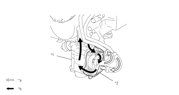
To suppress the increase of oil temperature while towing and to improve reliability, a water-cooled oil cooler is used.


b.

This oil cooler uses a square shaped laminated aluminum core to achieve lightweight, compact size, and a high heat radiation design.
W133012C01
2.271,2.24 2.885,2.396 true 3.958,2.896 4.521,3.25 true 2.031,2.115 2.344,2.271 0.313,0.156 10 false *1 4.604,3.25 4.917,3.406 0.313,0.156 10 false *2 0.656,3.135 0.969,3.292 0.313,0.156 10 false : *a 0.656,3.479 0.969,3.635 0.313,0.156 10 false : *b
*1 Oil Filter Bracket *2 Oil Cooler
*a Water Flow *b Engine Oil Flow