Home › General › ENGINE › 1UR-FE ENGINE
NM2660E _V1 General _054359 ENGINE _0265192 1UR-FE ENGINE UN GENERAL/CONTROL/DETAILS F

ENGINE  1UR-FE ENGINE  GENERAL/CONTROL/DETAILS  CHARGING SYSTEM  


General


a.

A compact and lightweight segment conductor type generator that generates high amperage output in a highly efficient manner is provided as standard equipment.


b.

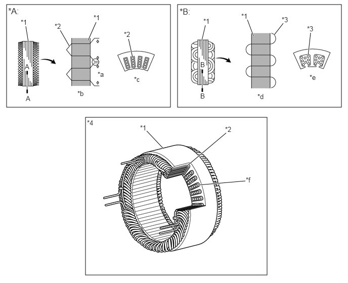
This generator has a joined segment conductor system in which multiple segment conductors are welded together to form the stator. Compared to the conventional winding system, the electrical resistance is reduced due to the shape of the segment conductors, and their arrangement helps to make the generator compact.
W128409C02
0.135,0.094 3.51,2.208 3.375,2.115 3.656,0.094 7.031,2.208 3.375,2.115 1.76,2.417 5.5,5.667 3.74,3.25 0.583,0.865 0.531,0.542 true 1.427,0.948 1.24,0.625 true 1.813,0.833 1.979,0.458 true 2.729,1.177 2.646,0.802 true 4.156,0.833 4.229,0.521 true 5.219,0.74 5.094,0.406 true 5.646,0.719 5.833,0.479 true 6.344,1.146 6.396,0.677 true 3.354,3.052 3.021,2.698 true 4.656,2.74 3.854,3.417 true 5.052,3.729 4.083,3.813 true 0.167,0.125 0.51,0.375 0.344,0.25 12 false *A: 3.698,0.135 4.042,0.385 0.344,0.25 12 false *B: 0.427,0.375 0.646,0.573 0.219,0.198 10 false *1 1.927,0.281 2.146,0.479 0.219,0.198 10 false *1 4.188,0.354 4.406,0.552 0.219,0.198 10 false *1 4.969,0.25 5.188,0.448 0.219,0.198 10 false *1 1.125,0.458 1.344,0.656 0.219,0.198 10 false *2 2.552,0.625 2.771,0.823 0.219,0.198 10 false *2 5.802,0.323 6.021,0.521 0.219,0.198 10 false *3 6.323,0.51 6.542,0.708 0.219,0.198 10 false *3 2.01,1.448 2.229,1.646 0.219,0.198 10 false *a 1.594,1.844 1.813,2.042 0.219,0.198 10 false *b 2.76,1.552 2.979,1.75 0.219,0.198 10 false *c 0.531,1.948 0.646,2.146 0.115,0.198 10 false A 4.125,1.896 4.24,2.063 0.115,0.167 10 false B 5.302,1.906 5.521,2.104 0.219,0.198 10 false *d 6.375,1.51 6.594,1.708 0.219,0.198 10 false *e 5.063,3.625 5.281,3.823 0.219,0.198 10 false *f 2.885,2.552 3.104,2.75 0.219,0.198 10 false *1 4.635,2.583 4.854,2.781 0.219,0.198 10 false *2 1.792,2.448 2.01,2.646 0.219,0.198 10 false *4 0.51,1.292 0.625,1.458 0.115,0.167 10 true A 4.125,1.25 4.24,1.417 0.115,0.167 10 true B
*A Segment Conductor Type Generator *B Conventional Type Generator
*1 Stator *2 Segment Conductor
*3 Conductor Wire *4 Stator of Segment Conductor Type Generator
*a Joined *b Joined Segment Conductor System
*c A - A CrossSection *d Winding System
*e B - B CrossSection *f Cross Section


Specifications
Type SC2
Rated Voltage 12 V
Rated Output 150 A
Initial Output Starting Speed Max. 1300 rpm

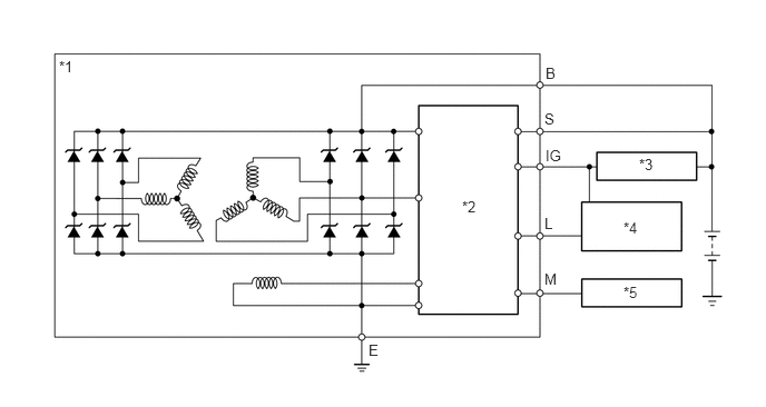
Wiring Diagram
W132958C01
0.552,0.542 0.865,0.698 0.313,0.156 10 false *1 5.833,2.052 6.146,2.208 0.313,0.156 10 false *4 5.833,2.656 6.146,2.813 0.313,0.156 10 false *5 5.104,0.604 5.417,0.76 0.313,0.156 10 false B 5.979,1.458 6.292,1.615 0.313,0.156 10 false *3 4.323,1.854 4.635,2.01 0.313,0.156 10 false *2 5.104,1.375 5.417,1.531 0.313,0.156 10 false IG 5.094,1.031 5.406,1.188 0.313,0.156 10 false S 5.094,2.01 5.406,2.167 0.313,0.156 10 false L 5.094,2.531 5.406,2.688 0.313,0.156 10 false M 3.448,3.198 3.76,3.354 0.313,0.156 10 false E
*1 Generator *2 Regulator
*3 Ignition Switch *4 Discharge Warning Light
*5 ECM - -


Dual Winding System


a.

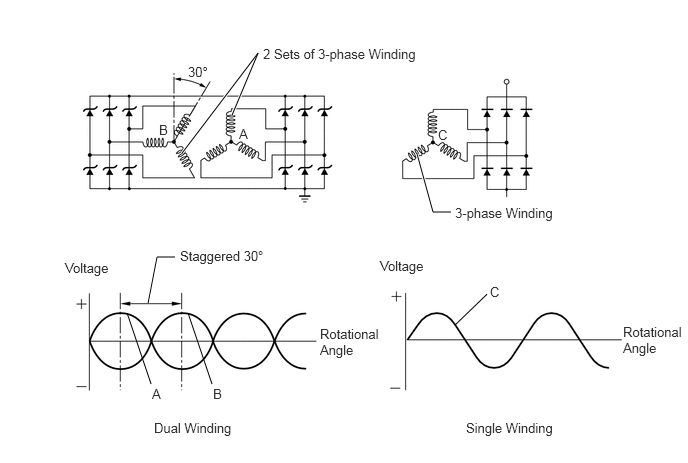
A dual winding system is used. This system consists of two sets of three-phase windings whose phases are staggered 30°. This system results in the reduction of both electrical noise (ripple and spike) and magnetic noise (a hum that is heard as generator load is increased). This system significantly suppresses noise at the source (generator). Because the waves that the respective windings generate have opposite polarities, magnetic noise is reduced. However, the electrical power generated does not cancel itself out due to the use of separate rectifiers. The opposite polarities that are generated are shown below:
W128411E01
1.896,1.594 2.688,0.552 2.688,0.552 2.417,1.198 true 4.698,2.208 4.51,2.208 4.51,2.208 4.344,1.604 true 1.542,3.156 1.635,2.677 1.635,2.677 1.823,2.677 false 1.573,4 1.323,3.26 false 2.208,4 1.958,3.26 false 5.073,3.063 4.74,3.385 false 2.74,0.479 4.375,0.844 1.635,0.365 10 false 2 Sets of 3-phase Winding 2.49,1.313 2.646,1.469 0.156,0.156 10 false A 1.656,1.271 1.781,1.448 0.125,0.177 10 false B 4.563,1.323 4.719,1.479 0.156,0.156 10 false C 1.958,0.667 2.177,0.875 0.219,0.208 10 false 30° 4.74,2.135 5.813,2.49 1.073,0.354 10 false 3-phase Winding 0.677,2.708 1.208,3.042 0.531,0.333 10 false Voltage 3.958,2.688 4.49,3.021 0.531,0.333 10 false Voltage 1.604,4.375 2.51,4.771 0.906,0.396 10 false Dual Winding 4.854,4.375 5.802,4.781 0.948,0.406 10 false Single Winding 1.875,2.583 2.802,2.927 0.927,0.344 10 false Staggered 30° 3.333,3.396 3.99,4.281 0.656,0.885 10 false Rotational Angle 6.49,3.375 7.146,4.26 0.656,0.885 10 false Rotational Angle 1.583,4.021 1.74,4.177 0.156,0.156 10 false A 2.219,4.021 2.344,4.198 0.125,0.177 10 false B 5.104,2.958 5.26,3.115 0.156,0.156 10 false C