Home › General › ENGINE › 1GR-FE ENGINE
NM2660E _V1 General _054359 ENGINE _0266961 1GR-FE ENGINE UN GENERAL/CONTROL/DETAILS F

ENGINE  1GR-FE ENGINE  GENERAL/CONTROL/DETAILS  INTAKE AND EXHAUST SYSTEM  


General


a.

Intake System

i.

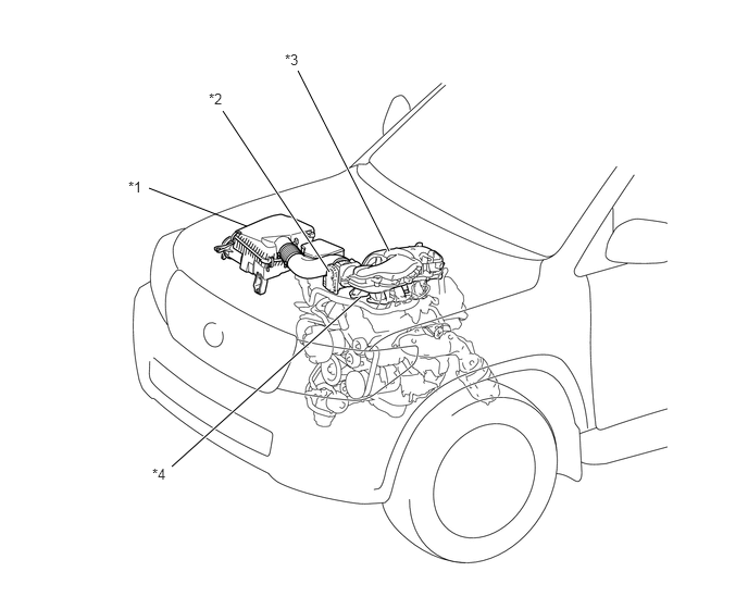
A linkless-type throttle body is used to achieve excellent throttle control.
W133221C01
2.365,2.167 1.427,1.802 false 3.156,2.604 2.135,1.063 true 3.729,2.406 2.854,0.677 true 1.646,4.469 3.458,2.844 true 1.229,1.708 1.604,2.01 0.375,0.302 10 false *1 2,0.865 2.458,1.24 0.458,0.375 10 false *2 2.729,0.49 3.188,0.708 0.458,0.219 10 false *3 1.458,4.458 1.771,4.656 0.313,0.198 10 false *4
*1 Air Cleaner Assembly *2 Throttle Body
*3 Intake Air Chamber *4 Intake Manifold


ii.

The Electronic Throttle Control System-intelligent (ETCS-i) is used to ensure excellent throttle control in all operating ranges.


b.

Exhaust System

i.

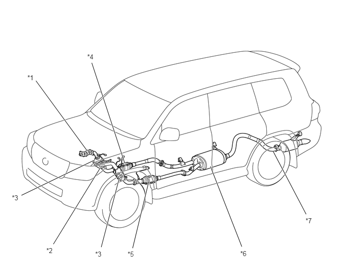
Stainless steel exhaust manifolds and exhaust pipes are used.
W133222C01
1.823,3.156 0.75,1.688 true 2.094,3.51 1.115,5.104 true 3.104,3.813 2.771,5.188 true 1.917,1.313 2.604,3.406 true 2.49,3.729 2.115,5.167 true 1.979,3.344 0.448,4.083 true 5.708,3.167 6.396,4.479 true 4.396,3.479 5.052,5.156 true 0.573,1.542 0.833,1.802 0.26,0.26 10 false *1 0.25,4.052 0.667,4.313 0.417,0.26 10 false *3 0.969,5.156 1.417,5.417 0.448,0.26 10 false *2 1.823,1.104 2.24,1.354 0.417,0.25 10 false *4 2.667,5.229 3.063,5.49 0.396,0.26 10 false *5 5.021,5.219 5.458,5.5 0.438,0.281 10 false *6 6.385,4.531 6.719,4.865 0.333,0.333 10 false *7 1.99,5.229 2.438,5.49 0.448,0.26 10 false *3
*1 Exhaust Manifold RH *2 Exhaust Manifold LH
*3 TWC *4 Front Exhaust Pipe Assembly
*5 Front No. 2 Exhaust Pipe Assembly *6 Center Exhaust Pipe Assembly
*7 Tail Pipe Assembly - -


ii.

An air injection pipe is used to the exhaust manifolds.


Air Cleaner


a.

A nonwoven, full-fabric type air cleaner element is used.


b.

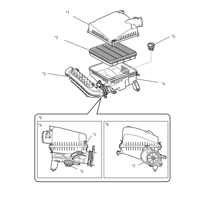
A cyclone pre-cleaner has been provided in the air cleaner case.* This cyclone pre-cleaner has a screw shape (turbinated blade) and gathers large dust particles in a dust cup by swirling the inlet air. The dust cup is removable from the inside of the air cleaner case, so the dust gathered can be disposed.

*: Models with pre-cleaner


c.

A rear duct is provided for the air cleaner inlet, thus enhancing anti-dust performance while keeping engine performance.
W132949C03
1.302,4.219 3.531,6.188 2.229,1.969 3.615,4.219 5.844,6.188 2.229,1.969 2.542,0.563 3.104,0.865 true 2.24,1.396 3.146,1.76 true 1.646,2.552 2.438,2.677 true 4.708,2.74 5.5,2.865 true 5.385,1.542 5.906,1.271 true 2.417,5.76 2.698,5.885 true 4.813,5.74 5.177,5.583 true 2.781,5.302 3.188,4.719 true 2.281,0.354 2.594,0.51 0.313,0.156 10 false *1 1.896,1.219 2.208,1.375 0.313,0.156 10 false *2 1.458,2.49 1.771,2.646 0.313,0.156 10 false *3 5.615,2.833 5.927,2.99 0.313,0.156 10 false *4 5.969,1.188 6.448,1.375 0.479,0.188 10 false *5 1.333,4.01 1.875,4.188 0.542,0.177 10 false *6 2.781,5.885 3.094,6.042 0.313,0.156 10 false *5 4.583,5.698 4.896,5.854 0.313,0.156 10 false *7 1.323,4.26 1.635,4.417 0.313,0.156 10 false *a 3.656,4.24 3.969,4.396 0.313,0.156 10 false *b 3.229,4.583 3.542,4.74 0.313,0.156 10 false *c
*1 Air Cleaner Cap *2 Air Cleaner Filter Element
*3 Air Cleaner Inlet *4 Air Cleaner Case
*5 Dust Cup *6 Cyclone Pre-cleaner
*7 Turbinated Blade - -
*a Rear View *b Side View
*c Swirl Air Flow - -


Throttle Body


a.

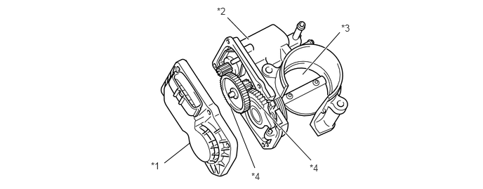
A link-less type throttle body in which the throttle position sensor and the throttle control motor are integrated is used. It realizes excellent throttle valve control.


b.

As a throttle control motor, a DC motor with excellent response and minimal power consumption is used. The ECM performs duty ratio control of the direction and the amperage of the current that is supplied to the throttle control motor in order to regulate the throttle valve angle.
W133223C01
2.438,2.417 2.823,2.115 false 3.427,1.604 3.781,2.49 true 3.375,0.26 3.688,0.583 true 3.844,1.552 4.615,2.375 true 4.49,1.104 5.042,0.479 true 2.24,2.375 2.677,2.635 0.438,0.26 10 false *1 3.219,0.083 3.563,0.323 0.344,0.24 10 false *2 5.063,0.333 5.448,0.563 0.385,0.229 10 false *3 4.594,2.406 4.927,2.615 0.333,0.208 10 false *4 3.729,2.531 4.063,2.74 0.333,0.208 10 false *4
*1 Throttle Position Sensor *2 DC Motor
*3 Throttle Valve *4 Reduction Gears


Intake Manifold


a.

Light weight aluminum alloy is used for the intake manifold.


b.

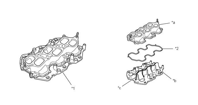
This intake manifold consists of two pieces, the upper and lower, which are sealed with a rubber gasket and adhesive.
W133224C01
4.417,3.135 4.917,2.802 true 5.885,2.615 6.198,2.865 true 5.875,1.771 6.26,1.771 true 5.76,0.896 6.146,0.833 true 2.583,3.083 2.25,2.594 true 2.583,3.125 2.99,3.438 0.406,0.313 10 false *1 6.333,1.677 6.74,1.99 0.406,0.313 10 false *2 6.208,0.729 6.521,0.969 0.313,0.24 10 false *a 6.25,2.844 6.563,3 0.313,0.156 10 false *b 4.26,3.104 4.698,3.417 0.438,0.313 10 false *c
*1 Intake Manifold *2 Rubber Gasket
*a Upper *b Lower
*c Adhesive - -


HINT:
·

Do not disassemble the upper and lower portions of the two-piece intake manifold, which are sealed with a rubber gasket and adhesive.

·

To remove the intake manifold assembly, remove the 10 bolts that are shown in the illustration.

·

These bolts have the head of hexagon shape.

W133225


Exhaust Manifold


a.

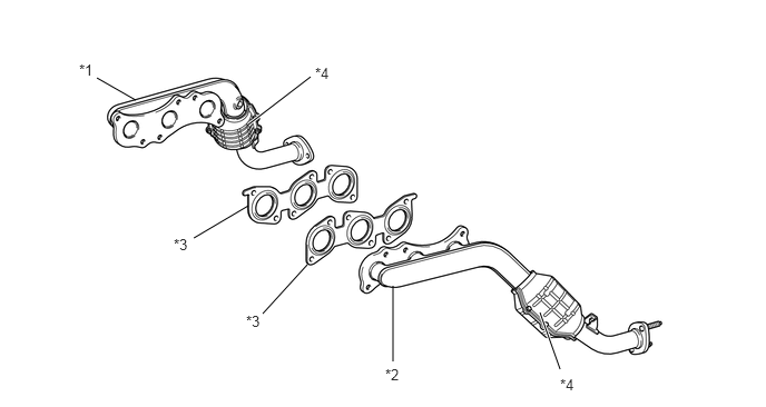
A stainless steel exhaust manifold is used for weight reduction and rust resistance.


b.

A ceramic type Three-Way Catalytic converter (TWC) is provided in each exhaust manifold for the right bank and the left bank.
W133226C01
1.813,2.229 2.323,1.927 false 2.458,2.938 2.875,2.479 false 5.24,3.458 5.052,2.927 true 3.677,3.385 3.677,2.677 false 0.906,0.729 1.271,0.938 false 2.323,1.167 2.906,0.719 true 0.74,0.573 1.073,0.781 0.333,0.208 10 false *1 3.604,3.427 3.958,3.677 0.354,0.25 10 false *2 1.625,2.208 1.969,2.469 0.344,0.26 10 false *3 5.24,3.521 5.5,3.719 0.26,0.198 10 false *4 2.302,2.927 2.646,3.188 0.344,0.26 10 false *3 2.948,0.604 3.208,0.802 0.26,0.198 10 false *4
*1 Exhaust Manifold Sub-assembly RH *2 Exhaust Manifold Sub-assembly LH
*3 Gasket *4 TWC


Exhaust Pipe


a.

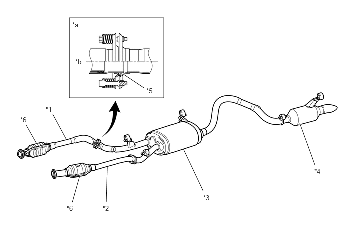
A stainless steel exhaust pipe is used for weight reduction and rust resistance.


b.

The ceramic type TWC is used.


c.

A ball joint is used to join the front exhaust pipe assembly and the center exhaust pipe assembly. As a result, a simple and reliable construction for reducing vibration has been realized.
W133227C01
1.438,0.365 3.406,2.031 1.969,1.667 2.552,1.531 2.99,1.823 true 0.542,2.604 0.76,2.99 true 1.656,3.656 1.5,4.208 true 2.229,3.469 2.208,4.198 true 1.094,2.375 1.375,2.896 true 3.802,3.094 4.219,3.979 true 6.229,2.563 6.542,3.427 true 0.948,2.188 1.26,2.417 0.313,0.229 10 false *1 2.135,4.25 2.51,4.5 0.375,0.25 10 false *2 4.219,4.031 4.583,4.313 0.365,0.281 10 false *3 6.531,3.479 6.865,3.781 0.333,0.302 10 false *4 3.042,1.802 3.417,2.063 0.375,0.26 10 false *5 1.385,4.25 1.781,4.552 0.396,0.302 10 false *6 1.5,0.427 1.885,0.74 0.385,0.313 10 false *a 1.563,1.198 1.906,1.49 0.344,0.292 10 false *b 0.417,2.406 0.813,2.708 0.396,0.302 10 false *6
*1 Front Exhaust Pipe Assembly *2 Front No. 2 Exhaust Pipe Assembly
*3 Center Exhaust Pipe Assembly *4 Tail Pipe Assembly
*5 Gasket *6 TWC
*a Ball Joint *b Front