BODY ELECTRICAL LIGHTING GENERAL/CONTROL/DETAILS LED HEADLIGHT SYSTEM
General
An LED headlight system, which is capable of instantly flashing and ensuring a long service life, is used in the low beam headlight for models with LED headlight system.
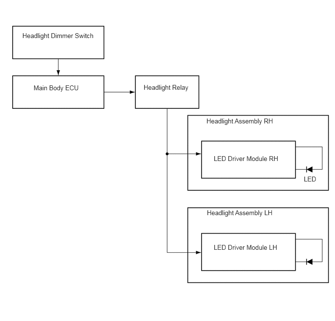
This system consists of a projector type LED headlight and LED driver module.
The LED driver module has a fail-safe function.
System Diagram
Layout of Main Components
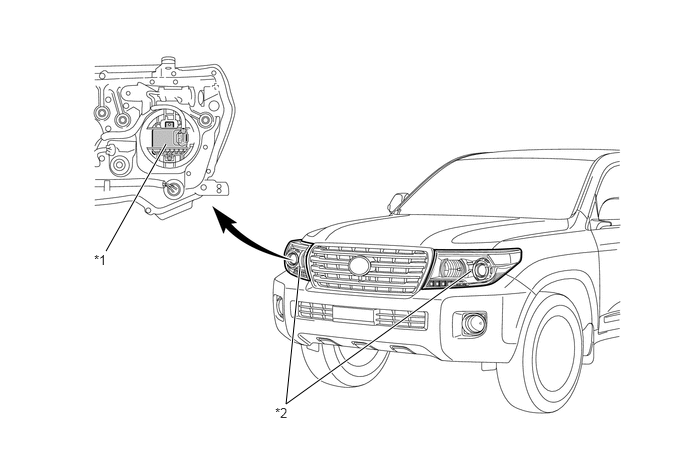
| *1 | LED Driver Module | *2 | Headlight Assembly RH |
Construction and Operation
Projector Type LED Light
One LED is used in the projector type LED light.
Through optimization of the reflector shape inside the lights, a large illumination range has been realized.
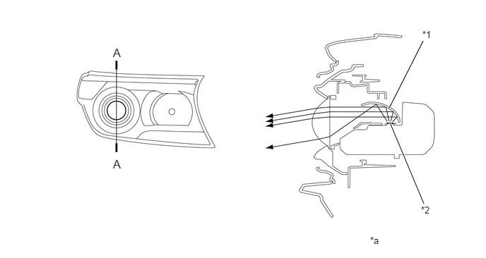
| *1 | Reflector | *2 | LED |
| *a | A - A Cross Section | - | - |
LED Driver Module
When the light control switch (headlight dimmer switch) is turned on, the LED driver modules immediately turn on the LEDs (approximately 0.1 seconds). In addition, by regulating the output currents flowing into the LEDs at the specified level, the LED driver modules prevent the glare of light due to voltage variation.
Fail-safe
The LED driver module executes the fail-safe actions listed below in accordance with the problem that has been detected.
| Problem | Outline |
|---|---|
| Detection of Abnormal Output (Open Circuit or Short Circuit) | If an abnormal condition (open or short) occurs in the voltage that is output by the LED driver module, the LED driver module stops illuminating the headlight and maintains its current state until an normal operation resumes. |
| Detection of Abnormal Input Voltage | If the voltage that is input to the LED driver module deviates from the normal operating voltage (17 V or more), the LED driver module stops illuminating the headlight. The LED driver module resumes illuminating the LED once the voltage reverts to the operating voltage range (10 V to 16 V). |
| If the voltage that is input to the LED driver module deviates from the normal operating voltage (8.5 V to 10 V), the LED driver module limits the output current. (The headlight will remain illuminated.) The LED driver module cancels the output current limit once the voltage reverts to the operating voltage range (10 V to 16 V). | |
| If the voltage that is input to the LED driver module deviates from the normal operating voltage (6 V or less), the LED driver module stops illuminating the headlight. The LED driver module resumes illuminating the LED once the voltage reverts to 8.5 V or more. |