Home › General › CHASSIS › TRANSFER
NM2660E _V1 General _054360 CHASSIS _0267095 TRANSFER UN GENERAL/CONTROL/DETAILS F

CHASSIS  TRANSFER  GENERAL/CONTROL/DETAILS  4WD CONTROL SYSTEM  


GENERAL


a.

The 4WD system is used, this system allows the driver to select the appropriate mode from among the four drive modes by utilizing the transfer position switch and center differential lock switch.


b.

Through these switch signals, the 4WD control ECU actuates the 2 shift motors in the transfer shift actuator assembly.


SYSTEM DIAGRAM
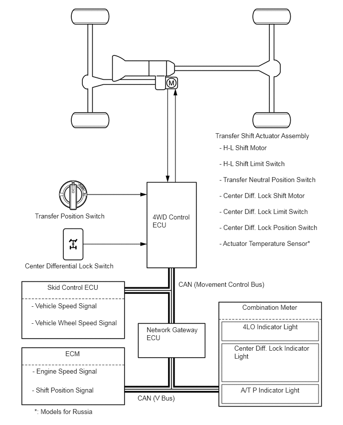

X133586E01
0.729,4.427 2.604,4.76 1.875,0.333 10 false Transfer Position Switch 0.521,5.469 2.708,5.802 2.188,0.333 10 false Center Differential Lock Switch 3.188,4.448 4.042,5.188 0.854,0.74 10 false 4WD Control ECU 4.5,2.75 6.917,3.167 2.417,0.417 10 false Transfer Shift Actuator Assembly 3.729,5.854 5.802,6.156 2.073,0.302 10 false CAN (Movement Control Bus) 5.063,6.333 6.583,6.667 1.521,0.333 10 false Combination Meter 5.073,6.74 6.594,7.073 1.521,0.333 10 false 4LO Indicator Light 4.896,7.188 6.542,7.646 1.646,0.458 10 false Center Diff. Lock Indicator Light 5.031,8.063 6.552,8.396 1.521,0.333 10 false A/T P Indicator Light 2.875,8.229 4.396,8.563 1.521,0.333 10 false CAN (V Bus) 3.063,6.802 4.219,7.354 1.156,0.552 10 false Network Gateway ECU 0.99,5.917 2.51,6.25 1.521,0.333 10 false Skid Control ECU 0.656,6.302 2.583,6.635 1.927,0.333 10 false - Vehicle Speed Signal 0.656,6.656 2.729,6.979 2.073,0.323 10 false - Vehicle Wheel Speed Signal 1.365,7.302 2.885,7.635 1.521,0.333 10 false ECM 0.677,7.667 2.51,8 1.833,0.333 10 false - Engine Speed Signal 0.667,8.063 2.458,8.385 1.792,0.323 10 false - Shift Position Signal 0.719,8.51 4.448,8.844 3.729,0.333 10 false *: Models for Russia 4.583,3 6.917,3.333 2.333,0.333 10 false - H-L Shift Motor 4.583,3.333 6.417,3.667 1.833,0.333 10 false - H-L Shift Limit Switch 4.583,3.667 6.667,4.083 2.083,0.417 10 false - Transfer Neutral Position Switch 4.583,4 6.75,4.5 2.167,0.5 10 false - Center Diff. Lock Shift Motor 4.583,4.333 6.917,4.833 2.333,0.5 10 false - Center Diff. Lock Limit Switch 4.583,4.667 7,5.083 2.417,0.417 10 false - Center Diff. Lock Position Switch 4.583,5 6.917,5.333 2.333,0.333 10 false - Actuator Temperature Sensor*


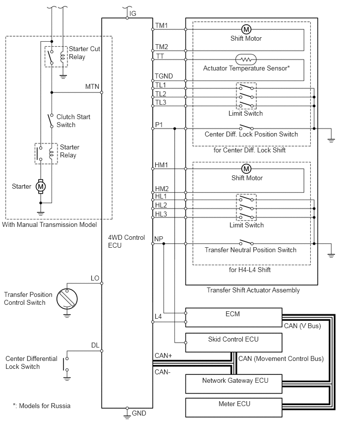
WIRING DIAGRAM


X133584E01
2.719,0.198 3.021,0.5 0.302,0.302 10 false IG 2.271,4.896 3.135,5.552 0.865,0.656 10 false 4WD Control ECU 1.448,0.938 2.167,1.438 0.719,0.5 10 false Starter Cut Relay 1.188,2.365 2.01,3.104 0.823,0.74 10 false Clutch Start Switch 1.26,3 1.74,3.479 0.479,0.479 10 false Starter Relay 0.25,3.823 0.792,4.344 0.542,0.521 10 false Starter 0.042,4.625 2.156,4.906 2.115,0.281 10 false With Manual Transmission Model 0.083,6.094 1.177,6.979 1.094,0.885 10 false Transfer Position Control Switch 0.115,7.438 1.25,7.948 1.135,0.51 10 false Center Differential Lock Switch 2.771,8.583 3.219,8.865 0.448,0.281 10 false GND 1.917,7.156 2.219,7.458 0.302,0.302 10 false DL 1.906,5.75 2.208,6.052 0.302,0.302 10 false LO 3.25,7.719 3.844,8.063 0.594,0.344 10 false CAN- 3.25,7.375 3.823,7.698 0.573,0.323 10 false CAN+ 5.969,6.75 7.01,7.302 1.042,0.552 10 false CAN (V Bus) 4.375,7.031 5.927,7.323 1.552,0.292 10 false Skid Control ECU 4.74,6.5 5.75,6.802 1.01,0.302 10 false ECM 4.25,7.896 6.177,8.302 1.927,0.406 10 false Network Gateway ECU 4.594,8.385 6.177,8.781 1.583,0.396 10 false Meter ECU 4.813,5.573 6.573,5.875 1.76,0.302 10 false for H4-L4 Shift 4.302,5.156 6.448,5.427 2.146,0.271 10 false Transfer Neutral Position Switch 4.344,6 6.719,6.229 2.375,0.229 10 false Transfer Shift Actuator Assembly 4.865,3.646 6.063,4 1.198,0.354 10 false Shift Motor 4.823,4.635 5.969,4.938 1.146,0.302 10 false Limit Switch 4.49,3.063 6.26,3.302 1.771,0.24 10 false for Center Diff. Lock Shift 4.302,2.729 6.417,3.052 2.115,0.323 10 false Center Diff. Lock Position Switch 4.802,2.292 6.115,2.656 1.313,0.365 10 false Limit Switch 4.271,1.344 6.24,1.635 1.969,0.292 10 false Actuator Temperature Sensor* 4.844,0.719 6.125,1.094 1.281,0.375 10 false Shift Motor 3.26,0.448 3.563,0.75 0.302,0.302 10 false TM1 3.26,0.896 3.563,1.198 0.302,0.302 10 false TM2 3.281,1.094 3.583,1.396 0.302,0.302 10 false TT 3.25,1.51 3.75,1.813 0.5,0.302 10 false TGND 3.26,1.698 3.563,2 0.302,0.302 10 false TL1 3.26,1.885 3.563,2.188 0.302,0.302 10 false TL2 3.26,2.063 3.563,2.365 0.302,0.302 10 false TL3 3.26,2.531 3.563,2.833 0.302,0.302 10 false P1 3.25,3.375 3.646,3.677 0.396,0.302 10 false HM1 3.26,3.875 3.635,4.167 0.375,0.292 10 false HM2 3.26,4.031 3.563,4.333 0.302,0.302 10 false HL1 3.26,4.219 3.563,4.521 0.302,0.302 10 false HL2 3.26,4.406 3.563,4.708 0.302,0.302 10 false HL3 3.24,4.927 3.542,5.229 0.302,0.302 10 false NP 3.25,6.552 3.552,6.854 0.302,0.302 10 false L4 1.792,1.729 2.094,2.031 0.302,0.302 10 false MTN 5.01,7.438 6.896,7.708 1.885,0.271 10 false CAN (Movement Control Bus) 0.271,8.427 1.771,8.667 1.5,0.24 10 false *: Models for Russia


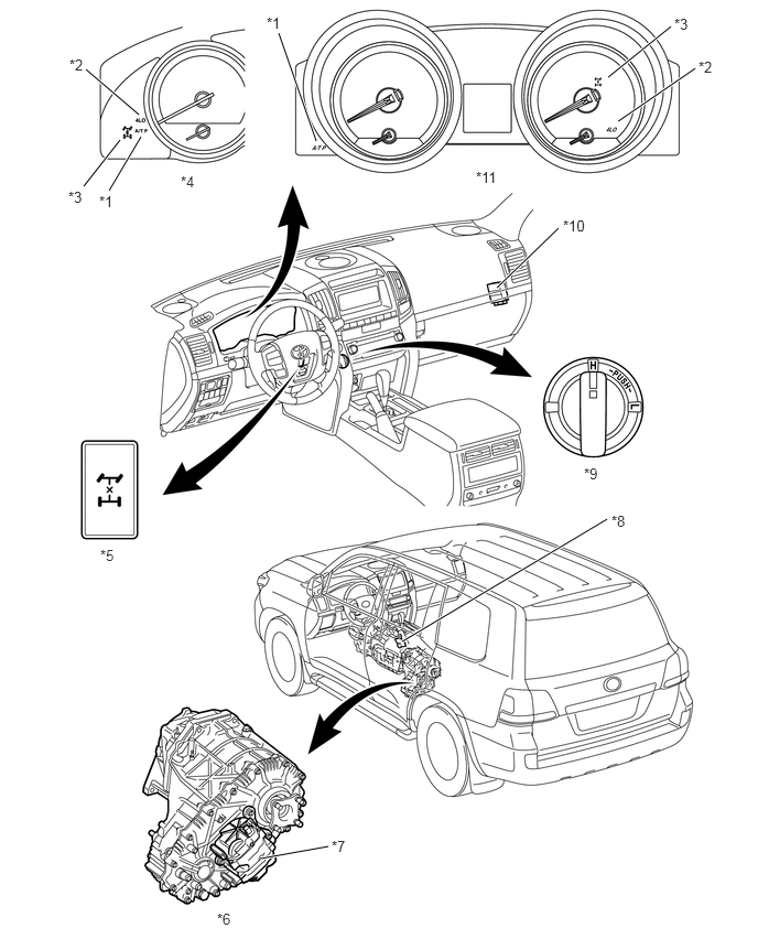
LAYOUT OF MAIN COMPONENTS


X133583C01
2.635,0.313 2.99,1.333 true 0.813,0.656 1.313,1.083 true 0.792,1.76 1.135,1.323 true 1.031,1.802 1.333,1.292 true 3.104,8 2.458,8.115 true 5.74,4.906 3.802,6.063 true 5.281,2.156 4.698,2.719 true 6.344,0.25 5.75,0.729 true 6.573,0.646 5.844,1.146 true 2.521,0.135 2.833,0.292 0.313,0.156 10 false *1 0.656,0.531 0.969,0.688 0.313,0.156 10 false *2 0.646,1.781 0.958,1.938 0.313,0.156 10 false *3 0.948,5.167 1.26,5.323 0.313,0.156 10 false *5 2.052,8.604 2.365,8.76 0.313,0.156 10 false *6 3.135,7.917 3.448,8.073 0.313,0.156 10 false *7 5.781,4.844 6.094,5 0.313,0.156 10 false *8 5.521,4.396 5.833,4.552 0.313,0.156 10 false *9 5.323,2.052 5.635,2.208 0.313,0.156 10 false *10 4.5,1.594 4.969,1.75 0.469,0.156 10 false *11 0.938,1.823 1.25,1.979 0.313,0.156 10 false *1 6.375,0.146 6.688,0.302 0.313,0.156 10 false *3 6.604,0.552 6.917,0.708 0.313,0.156 10 false *2 1.708,1.635 2.177,1.792 0.469,0.156 10 false *4
*1 A/T P Indicator Light *2 4LO Indicator Light
*3 Center Diff. Lock Indicator Light *4 Analog Type Combination Meter
*5 Center Differential Lock Switch *6 JF2A Transfer
*7 Transfer Shift Actuator Assembly
·

H-L Shift Motor

·

H-L Shift Limit Switch

·

Transfer Neutral Position Switch

·

Center Diff. Lock Shift Motor

·

Center Diff. Lock Limit Switch

·

Center Diff. Lock Position Switch

·

Actuator Temperature Sensor (Models for Russia)


*8 Park/ Neutral Position Switch
*9 Transfer Position Switch *10 4WD Control ECU
*11 Optitron Display Type Combination Meter - -


SYSTEM OPERATION


a.

General

i.

The 4WD mode switching pattern of this system is as shown in the illustration below. The system operation of each switching pattern is explained from the next page.


ii.

When the vehicle speed is below approximately 100km/h (62mph), free-lock switching of the center differential lock (switching patterns A to D) is available while the vehicle is running.


iii.

The H4-L4 switching of the transfer gear ratio (switching patterns E to H) is available only when the vehicle is stationary and the shift position is N*.

*: For models equipped with the manual transmission, when the vehicle is stationary and the clutch pedal is being depressed.
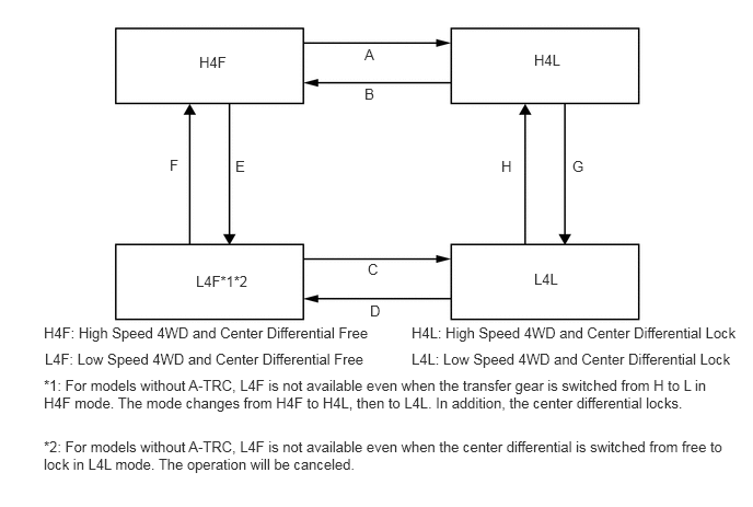

4WD Mode Switching Pattern
X132325E03
1.896,0.51 2.313,0.844 0.417,0.333 10 false H4F 1.865,2.594 2.583,2.917 0.719,0.323 10 false L4F*1*2 5.083,2.573 5.552,2.958 0.469,0.385 10 false L4L 5.083,0.49 5.583,0.844 0.5,0.354 10 false H4L 3.469,0.813 3.76,1.083 0.292,0.271 10 false B 1.615,1.49 1.833,1.74 0.219,0.25 10 false F 2.24,1.5 2.51,1.771 0.271,0.271 10 false E 3.469,0.438 3.719,0.698 0.25,0.26 10 false A 4.771,1.5 4.99,1.771 0.219,0.271 10 false H 5.448,1.5 5.719,1.802 0.271,0.302 10 false G 0.417,3.083 3.75,3.417 3.333,0.333 10 false H4F: High Speed 4WD and Center Differential Free 3.917,3.083 7.156,3.417 3.24,0.333 10 false H4L: High Speed 4WD and Center Differential Lock 0.427,3.333 3.667,3.667 3.24,0.333 10 false L4F: Low Speed 4WD and Center Differential Free 3.917,3.333 7.156,3.667 3.24,0.333 10 false L4L: Low Speed 4WD and Center Differential Lock 3.5,2.479 3.76,2.719 0.26,0.24 10 false C 3.521,2.875 3.813,3.156 0.292,0.281 10 false D 0.417,3.583 6.917,4.083 6.5,0.5 10 false *1: For models without A-TRC, L4F is not available even when the transfer gear is switched from H to L in H4F mode. The mode changes from H4F to H4L, then to L4L. In addition, the center differential locks. 0.417,4.167 6.917,4.583 6.5,0.417 10 false *2: For models without A-TRC, L4F is not available even when the center differential is switched from free to lock in L4L mode. The operation will be canceled.


b.

Switching Pattern : A (H4F → H4L)

i.

In H4F mode, when the center differential lock switch is turned on, the 4WD control ECU actuates the center differential lock shift motor to move the center differential lock shift fork shaft right. Simultaneously, the shift fork moves right together with the fork shaft. As a result, the center differential lock sleeve engages the differential case and the drive sprocket hub, and the mode changes to H4L.


ii.

The 4WD control ECU detects the state of the center differential through the limit switch and center differential lock position switch. The 4WD control ECU causes the center differential lock indicator light to turn ON when the center differential is locked.
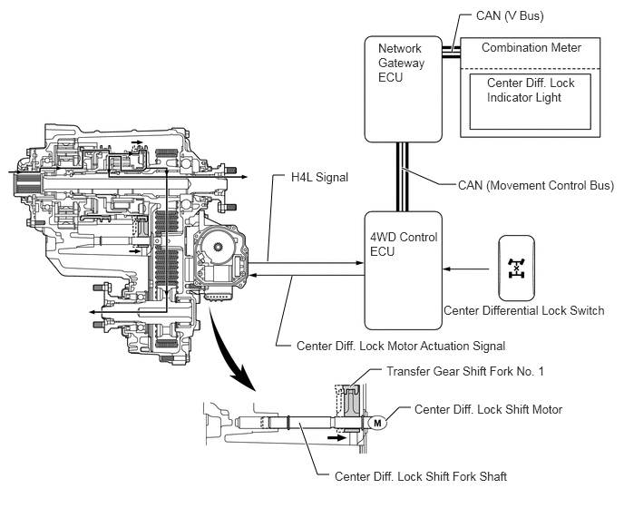
X133587E01
3.073,3 3.135,2.01 3.135,2.01 3.271,2.01 true 5.188,0.594 5.281,0.167 5.281,0.167 5.417,0.167 true 4.615,1.927 5.042,2.115 5.042,2.115 5.24,2.115 true 3.354,3.167 3.167,3.969 3.167,3.969 3.344,3.969 true 4.021,4.438 4.25,4.24 4.25,4.24 4.385,4.24 true 4.427,4.833 4.583,4.677 4.583,4.677 4.719,4.677 true 3.438,4.854 3.646,5.448 3.646,5.448 3.781,5.448 true 5.469,0.094 7.156,0.292 1.688,0.198 10 false CAN (V Bus) 5.531,0.458 6.948,0.729 1.417,0.271 10 false Combination Meter 5.594,0.865 6.677,1.438 1.083,0.573 10 false Center Diff. Lock Indicator Light 4.344,0.469 4.958,1.479 0.615,1.01 10 false Network Gateway ECU 5.26,2.042 7.146,2.51 1.885,0.469 10 false CAN (Movement Control Bus) 5.094,3.479 7.063,3.698 1.969,0.219 10 false Center Differential Lock Switch 4.25,2.635 5.125,3.167 0.875,0.531 10 false 4WD Control ECU 3.344,1.948 4.292,2.323 0.948,0.375 10 false H4L Signal 3.406,3.885 6.594,4.115 3.188,0.229 10 false Center Diff. Lock Motor Actuation Signal 4.438,4.177 6.51,4.458 2.073,0.281 10 false Transfer Gear Shift Fork No. 1 4.76,4.615 6.583,5.01 1.823,0.396 10 false Center Diff. Lock Shift Motor 3.844,5.385 6.313,5.719 2.469,0.333 10 false Center Diff. Lock Shift Fork Shaft


c.

Switching Pattern : B (H4L → H4F)

i.

In H4L mode, when the center differential lock switch is turned off, the 4WD control ECU actuates the center differential lock shift motor to move the center differential lock shift fork shaft left. Simultaneously, the shift fork moves left together with the fork shaft. As a result, the center differential lock sleeve disengages the differential case and the drive sprocket hub, and the mode changes to H4F.


ii.

The 4WD control ECU detects the state of the center differential through the limit switch and center differential lock position switch. The 4WD control ECU causes the center differential lock indicator light to turn OFF when the center differential is unlocked.
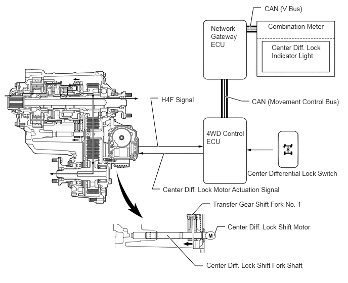
X133593E01
4.198,5.125 3.979,5.125 3.979,5.125 3.969,4.479 true 4.635,4.667 4.479,4.667 4.479,4.667 4.406,4.865 true 4.323,4.198 4.167,4.198 4.167,4.198 3.948,4.438 true 3.292,3.896 3.135,3.896 3.135,3.896 3.375,3.156 true 3.26,2.021 3.104,2.021 3.104,2.021 3.25,3.021 true 5.375,0.156 5.219,0.156 5.219,0.156 5.146,0.604 true 5.135,2.083 4.979,2.083 4.979,2.083 4.625,1.979 true 4.177,5.479 4.021,5.479 4.021,5.479 3.438,4.844 true 5.188,2.01 7.073,2.354 1.885,0.344 10 false CAN (Movement Control Bus) 5.521,0.458 6.979,0.813 1.458,0.354 10 false Combination Meter 5.594,0.896 6.677,1.375 1.083,0.479 10 false Center Diff. Lock Indicator Light 4.344,0.5 4.948,1.344 0.604,0.844 10 false Network Gateway ECU 5.448,0.094 6.438,0.375 0.99,0.281 10 false CAN (V Bus) 4.25,2.667 5.125,3.302 0.875,0.635 10 false 4WD Control ECU 5.094,3.49 7.073,3.844 1.979,0.354 10 false Center Differential Lock Switch 4.385,4.125 6.479,4.417 2.094,0.292 10 false Transfer Gear Shift Fork No. 1 4.688,4.594 6.573,4.938 1.885,0.344 10 false Center Diff. Lock Shift Motor 4.25,5.385 6.833,5.667 2.583,0.281 10 false Center Diff. Lock Shift Fork Shaft 3.354,3.823 6.365,4.063 3.01,0.24 10 false Center Diff. Lock Motor Actuation Signal 3.323,1.969 4.177,2.313 0.854,0.344 10 false H4F Signal


d.

Switching Pattern : C (L4F → L4L)

i.

In L4F mode, when the center differential lock switch is turned on, the 4WD control ECU actuates the center differential shift motor to move the center differential lock shift fork shaft right. Simultaneously, the shift fork moves right together with the fork shaft. As a result, the center differential lock sleeve engages the center differential case and the drive sprocket hub, and the mode changes to L4L.


ii.

The 4WD control ECU detects the state of the center differential through the limit switch and center differential lock position switch. The 4WD control ECU causes the center differential lock indicator light to turn ON when the center differential is locked.
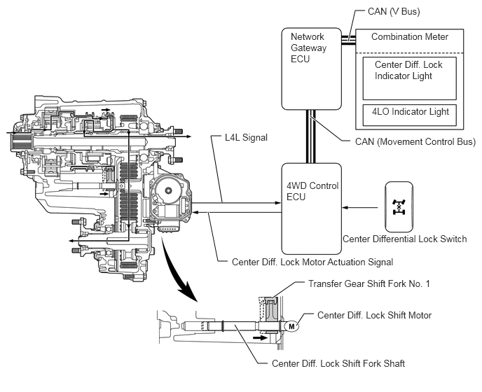
X133588E01
5.177,0.615 5.281,0.156 5.281,0.156 5.427,0.156 true 3.302,3.01 3.135,2.021 3.135,2.021 3.292,2.021 true 3.094,3.156 3.24,3.885 3.24,3.885 3.385,3.885 true 4.615,1.729 5.083,2.094 5.083,2.094 5.208,2.094 true 4.042,4.438 4.385,4.198 4.385,4.198 4.531,4.198 true 4.406,4.844 4.521,4.667 4.521,4.667 4.667,4.667 true 3.49,4.833 3.833,5.406 3.833,5.406 3.979,5.406 true 5.469,0.083 6.99,0.365 1.521,0.281 10 false CAN (V Bus) 5.521,0.458 7.042,0.688 1.521,0.229 10 false Combination Meter 5.573,0.875 6.667,1.458 1.094,0.583 10 false Center Diff. Lock Indicator Light 5.531,1.573 7.073,1.802 1.542,0.229 10 false 4LO Indicator Light 4.323,0.458 4.938,1.333 0.615,0.875 10 false Network Gateway ECU 3.344,1.958 4.26,2.219 0.917,0.26 10 false L4L Signal 4.26,2.677 5.094,3.24 0.833,0.563 10 false 4WD Control ECU 5.094,3.469 7.042,3.708 1.948,0.24 10 false Center Differential Lock Switch 5.281,2.021 7.146,2.271 1.865,0.25 10 false CAN (Movement Control Bus) 3.448,3.813 6.292,3.99 2.844,0.177 10 false Center Diff. Lock Motor Actuation Signal 4.583,4.135 6.542,4.323 1.958,0.188 10 false Transfer Gear Shift Fork No. 1 4.719,4.604 6.542,4.99 1.823,0.385 10 false Center Diff. Lock Shift Motor 4.042,5.323 6.385,5.583 2.344,0.26 10 false Center Diff. Lock Shift Fork Shaft


e.

Switching Pattern : D (L4L → L4F)

i.

In L4L mode, when the center differential lock switch is turned off, the 4WD control ECU actuates the center differential lock shift motor to move the center differential lock shift fork shaft left. Simultaneously, the shift fork moves left together with the fork shaft. As a result, the center differential lock sleeve disengages the differential case and the drive sprocket hub, and the mode changes to L4F.


ii.

The 4WD control ECU detects the state of the center differential through the limit switch and center differential lock position switch. The 4WD control ECU causes the center differential lock indicator light to turn OFF when the center differential is unlocked.
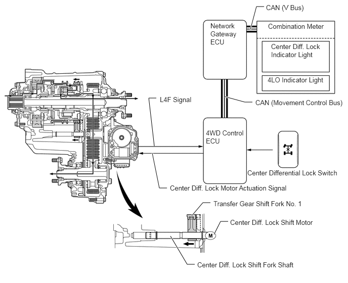
X133594E01
3.948,4.448 4.177,4.177 4.177,4.177 4.333,4.177 true 4.406,4.833 4.542,4.563 4.542,4.563 4.698,4.563 true 3.51,4.865 3.854,5.448 3.854,5.448 4.01,5.448 true 3.177,3.01 3.063,2.021 3.063,2.021 3.219,2.021 true 3.135,3.156 3.281,3.875 3.281,3.875 3.438,3.875 true 5.156,0.604 5.281,0.135 5.281,0.135 5.438,0.135 true 4.625,1.99 5.042,2.104 5.042,2.104 5.198,2.104 true 5.479,0.073 6.74,0.354 1.26,0.281 10 false CAN (V Bus) 5.521,0.458 7.031,0.698 1.51,0.24 10 false Combination Meter 5.583,0.875 6.667,1.302 1.083,0.427 10 false Center Diff. Lock Indicator Light 5.51,1.563 6.938,1.781 1.427,0.219 10 false 4LO Indicator Light 4.333,0.448 4.927,1.25 0.594,0.802 10 false Network Gateway ECU 4.24,2.656 5.073,3.188 0.833,0.531 10 false 4WD Control ECU 5.094,3.479 7.073,3.719 1.979,0.24 10 false Center Differential Lock Switch 4.396,4.115 6.438,4.375 2.042,0.26 10 false Transfer Gear Shift Fork No. 1 3.5,3.792 6.333,3.99 2.833,0.198 10 false Center Diff. Lock Motor Actuation Signal 4.74,4.5 6.615,4.792 1.875,0.292 10 false Center Diff. Lock Shift Motor 4.063,5.375 6.635,5.646 2.573,0.271 10 false Center Diff. Lock Shift Fork Shaft 3.292,1.969 4.979,2.167 1.688,0.198 10 false L4F Signal 5.26,2.031 7.125,2.281 1.865,0.25 10 false CAN (Movement Control Bus)


f.

Switching Pattern : E (H4F → L4F)

i.

In H4F mode, when the transfer position switch is turned to the 4L position, the 4WD control ECU actuates the H-L shift motor to move the H-L shift fork shaft right. Simultaneously, the shift fork moves right together with fork shaft. As a result, the high and low clutch sleeve of the planetary gear unit engages with the planetary carrier, and the mode changes to L4F.


ii.

The 4WD control ECU detects the state of the H-L position through the limit switch and transfer neutral position switch. The 4WD control ECU causes the 4LO indicator light to turn ON when the transfer to the L4F mode has been completed.
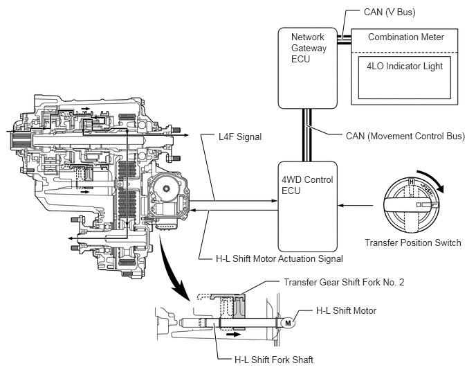
X133589E01
5.146,0.604 5.208,0.156 5.208,0.156 5.417,0.156 true 4.615,1.885 4.948,2.021 4.948,2.021 5.156,2.021 true 3.229,3.01 3.021,2.021 3.021,2.021 3.229,2.021 true 3.604,4.438 4,4.229 4,4.229 4.208,4.229 true 3.146,3.156 2.99,3.896 2.99,3.896 3.198,3.896 true 4.406,4.844 4.5,4.667 4.5,4.667 4.708,4.667 true 3.219,4.854 3.281,5.396 3.281,5.396 3.49,5.396 true 5.479,0.094 6.833,0.385 1.354,0.292 10 false CAN (V Bus) 5.542,0.469 6.896,0.76 1.354,0.292 10 false Combination Meter 5.521,0.906 6.875,1.198 1.354,0.292 10 false 4LO Indicator Light 4.385,0.469 4.979,1.323 0.594,0.854 10 false Network Gateway ECU 4.24,2.615 5.083,3.427 0.844,0.813 10 false 4WD Control ECU 5.49,3.563 7.052,3.979 1.563,0.417 10 false Transfer Position Switch 5.208,1.958 7.115,2.292 1.906,0.333 10 false CAN (Movement Control Bus) 3.292,1.969 4.646,2.26 1.354,0.292 10 false L4F Signal 3.25,3.802 5.583,4.042 2.333,0.24 10 false H-L Shift Motor Actuation Signal 4.271,4.156 6.146,4.5 1.875,0.344 10 false Transfer Gear Shift Fork No. 2 4.76,4.583 6.115,4.875 1.354,0.292 10 false H-L Shift Motor 3.531,5.323 4.885,5.615 1.354,0.292 10 false H-L Shift Fork Shaft


g.

Switching Pattern : F (L4F → H4F)

i.

In L4F mode, when the transfer position switch is turned to the 4H position, the 4WD control ECU actuates the H-L shift motor to move the H-L shift fork shaft left. Simultaneously, shift fork moves left together with the fork shaft. As a result, the high and low clutch sleeve of the planetary gear unit engages with the input shaft, and the mode changes to H4F.


ii.

The 4WD control ECU detects the state of the H-L position through the limit switch and transfer neutral position switch. The 4WD control ECU causes the 4LO indicator light to turn OFF when the transfer to the H4F mode has been completed.
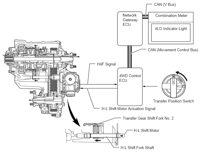
X133590E01
3.125,3 3.198,2.281 3.198,2.281 3.396,2.281 true 5.188,0.604 5.229,0.146 5.229,0.146 5.427,0.146 true 4.625,1.927 5.021,1.76 5.021,1.76 5.219,1.76 true 3.104,3.156 3.354,3.875 3.354,3.875 3.552,3.875 true 3.406,4.458 4.115,4.219 4.115,4.219 4.313,4.219 true 4.417,4.844 4.542,4.656 4.542,4.656 4.74,4.656 true 3.781,4.875 4.052,5.271 4.052,5.271 4.25,5.271 true 5.49,0.073 6.75,0.323 1.26,0.25 10 false CAN (V Bus) 5.542,0.469 7.063,0.813 1.521,0.344 10 false Combination Meter 5.521,0.938 7.042,1.24 1.521,0.302 10 false 4LO Indicator Light 4.375,0.458 5.031,1.5 0.656,1.042 10 false Network Gateway ECU 4.25,2.625 5.094,3.302 0.844,0.677 10 false 4WD Control ECU 5.458,3.531 7.094,3.802 1.635,0.271 10 false Transfer Position Switch 3.625,3.802 6.094,4.042 2.469,0.24 10 false H-L Shift Motor Actuation Signal 4.375,4.146 6.656,4.438 2.281,0.292 10 false Transfer Gear Shift Fork No. 2 4.771,4.583 6.458,4.781 1.688,0.198 10 false H-L Shift Motor 4.302,5.198 5.99,5.396 1.688,0.198 10 false H-L Shift Fork Shaft 5.271,1.698 7.146,1.969 1.875,0.271 10 false CAN (Movement Control Bus) 3.458,2.208 5.146,2.406 1.688,0.198 10 false H4F Signal


h.

Switching Pattern : G (H4L → L4L)

i.

In H4L mode, when the transfer position switch is turned to the 4L position, the 4WD control ECU actuates the H-L shift motor to move the H-L shift fork shaft right. Simultaneously, the shift fork moves right together with the fork shaft. As a result, the high and low clutch sleeve of the planetary gear unit engages with the planetary carrier, and the mode changes to L4L.


ii.

The 4WD control ECU detects the state of the H-L position through the limit switch and transfer neutral position switch. The 4WD control ECU causes the 4LO indicator light to turn ON when the transfer to the L4L mode has been completed.
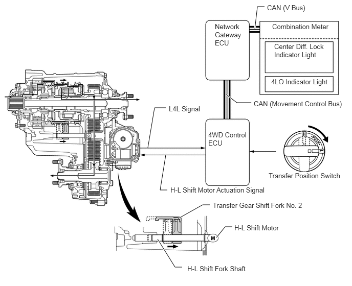
X133591E01
5.188,0.583 5.24,0.135 5.24,0.135 5.385,0.135 true 3.375,3.156 3.26,3.875 3.26,3.875 3.406,3.875 true 3.625,4.458 4.125,4.177 4.125,4.177 4.271,4.177 true 4.406,4.844 4.583,4.625 4.583,4.625 4.729,4.625 true 3.208,4.875 3.563,5.448 3.563,5.448 3.708,5.448 true 3.01,3.01 3.146,2.198 3.146,2.198 3.375,2.198 true 5.115,2.094 4.823,2.094 4.823,2.094 4.604,1.927 true 5.438,0.073 6.51,0.396 1.073,0.323 10 false CAN (V Bus) 5.542,0.458 6.906,0.792 1.365,0.333 10 false Combination Meter 5.583,0.865 6.667,1.292 1.083,0.427 10 false Center Diff. Lock Indicator Light 5.521,1.583 6.938,1.906 1.417,0.323 10 false 4LO Indicator Light 5.469,3.5 7.146,3.792 1.677,0.292 10 false Transfer Position Switch 4.375,0.458 4.99,1.271 0.615,0.813 10 false Network Gateway ECU 4.24,2.667 5.063,3.208 0.823,0.542 10 false 4WD Control ECU 5.167,2.031 7.042,2.417 1.875,0.385 10 false CAN (Movement Control Bus) 3.438,2.135 4.51,2.458 1.073,0.323 10 false L4L Signal 3.469,3.792 5.708,4.156 2.24,0.365 10 false H-L Shift Motor Actuation Signal 4.333,4.104 6.292,4.344 1.958,0.24 10 false Transfer Gear Shift Fork No. 2 4.771,4.563 5.844,4.885 1.073,0.323 10 false H-L Shift Motor 3.813,5.396 5.542,5.698 1.729,0.302 10 false H-L Shift Fork Shaft


i.

Switching Pattern : H (L4L → H4L)

i.

In L4L mode, the transfer position switch is turned to the 4H position, the 4WD control ECU actuates the H-L shift motor to move the H-L shift fork shaft left. Simultaneously, the shift fork moves left together with the fork shaft. As a result, the high and low clutch sleeve of the planetary gear unit engages with the input shaft, and the mode changes to H4L.


ii.

The 4WD control ECU detects the state of the H-L position through the limit switch and transfer neutral position switch. The 4WD control ECU causes the 4LO indicator light to turn OFF when the transfer to the H4L mode has been completed.
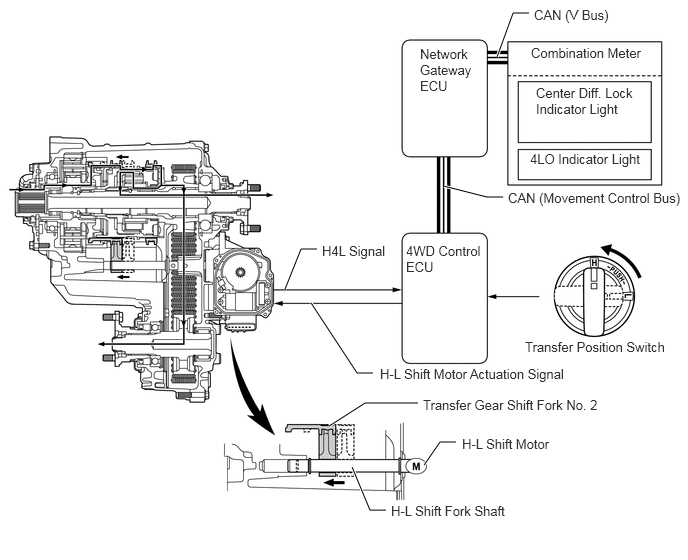
X133592E01
3.24,3.156 3.719,3.885 3.719,3.885 3.885,3.885 true 3.427,4.438 3.802,4.198 3.802,4.198 4.354,4.198 true 4.417,4.844 4.583,4.604 4.583,4.604 4.75,4.604 true 3.667,4.865 3.854,5.313 3.854,5.313 4.021,5.313 true 5.177,0.594 5.344,0.135 5.344,0.135 5.51,0.135 true 4.625,1.938 5.073,2.052 5.073,2.052 5.24,2.052 true 2.969,3.01 3.135,2.594 3.135,2.594 3.302,2.594 true 5.563,0.073 6.969,0.271 1.406,0.198 10 false CAN (V Bus) 5.531,0.469 7.042,0.781 1.51,0.313 10 false Combination Meter 5.583,0.885 6.688,1.396 1.104,0.51 10 false Center Diff. Lock Indicator Light 5.521,1.573 7.125,1.948 1.604,0.375 10 false 4LO Indicator Light 5.469,3.531 7.156,3.729 1.688,0.198 10 false Transfer Position Switch 4.375,0.479 4.99,1.448 0.615,0.969 10 false Network Gateway ECU 4.229,2.531 5.073,3.135 0.844,0.604 10 false 4WD Control ECU 5.292,1.979 7.156,2.375 1.865,0.396 10 false CAN (Movement Control Bus) 3.354,2.531 5.042,2.729 1.688,0.198 10 false H4L Signal 3.958,3.813 6.51,4.094 2.552,0.281 10 false H-L Shift Motor Actuation Signal 4.813,4.542 6.5,4.74 1.688,0.198 10 false H-L Shift Motor 4.406,4.135 6.844,4.385 2.438,0.25 10 false Transfer Gear Shift Fork No. 2 4.073,5.24 5.76,5.438 1.688,0.198 10 false H-L Shift Fork Shaft