Home › General › NEW FEATURES [2015/08 Update] › NEW FEATURES › from 2015.08
NM2660E _V1 General _054961 NEW FEATURES [2015/08 Update] _0267699 NEW FEATURES UN GENERAL/CONTROL/DETAILS F

NEW FEATURES [2015/08 Update]  NEW FEATURES  GENERAL/CONTROL/DETAILS  1UR-FE ENGINE  


DESCRIPTION


a.

Specifications for 1UR-FE engine for the models for Europe have been modified for compliance with EURO 6 regulations from EURO 5 regulations.


b.

Specifications for 1UR-FE engine for the models for Russia, Ukraine, Kazakhstan and Australia have been modified for compliance with EURO 5 regulations from EURO 4 regulations.


c.

Specifications for 1UR-FE engine for the models for Peru have been modified for compliance with EURO 5 regulations from EURO 4 regulations.

*1: The figure shown is the weight of the part without water and oil.

*2: Models compliant with EURO 5 and EURO 6 emission regulations

*3: Models compliant with CHINA 5 emission regulations

*4: Except models compliant with EURO 5, EURO 6 and CHINA 5 emission regulations

*5: Emission regulations differ by country and region

No. of Cyls. & Arrangement 8-cylinder, V Type
Valve Mechanism 32-valve DOHC, Chain Drive (with Dual VVT-i)
Combustion Chamber Pentroof Type
Manifolds Cross-flow
Fuel System EFI
Ignition System DIS
Displacement 4608 cm3 (281.2 cu. in.)
Bore x Stroke 94.0 mm x 83.0 mm (3.70 in. x 3.27 in.)
Compression Ratio 10.2 : 1
Max. Output (ECC) 234 kW @ 5600 rpm*2
228 kW @ 5500 rpm*3
227 kW @ 5500 rpm*4
Max. Torque (ECC) 460 N*m @ 3400 rpm*2
453 N*m @ 3400 rpm*3
439 N*m @ 3400 rpm*4
Valve Timing Intake Open - 18° to 22° BTDC
Closed 70° to 30° ABDC
Exhaust Open 62° to 30° BBDC
Closed - 8° to 24° ATDC
Firing Order 1 - 8 - 7 - 3 - 6 - 5 - 4 - 2
Research Octane Number (RON) 95 or higher*2
97 or higher*3
91 or higher*4
Emission Regulations*5 EURO 2
EURO 3
EURO 4
EURO 5
EURO 6
CHINA 5
Engine Service Mass (Reference)*1 216 kg (476.2 lb)


ENGINE CONTROL SYSTEM


a.

General

i.

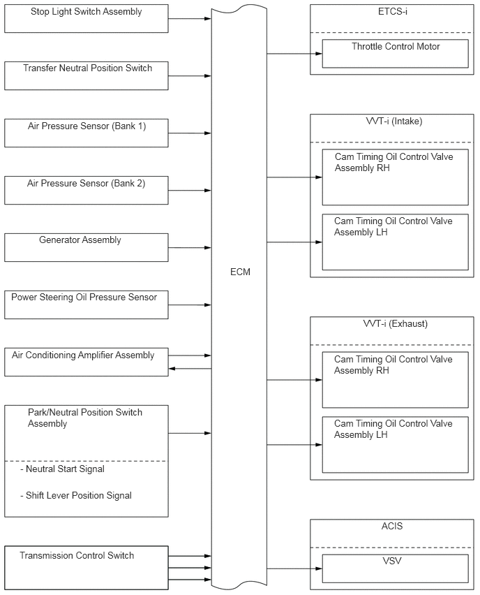
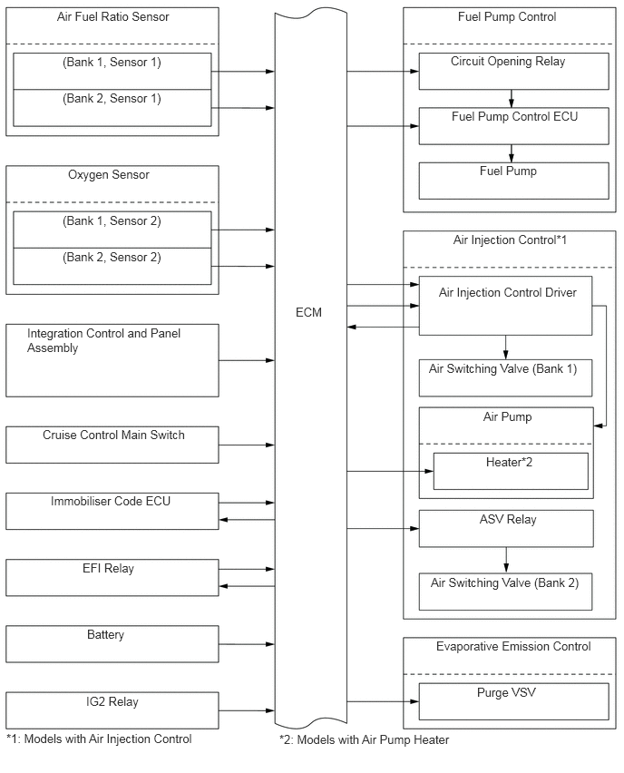
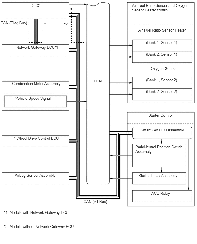
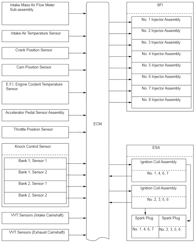
Part of the circuit has been altered along with the new Controller Area Network (CAN) communication system.


b.

Construction

i.

The configuration of the engine control system is as shown in the following chart:
W133303E01
0.365,0.094 2.208,0.875 1.844,0.781 10 false Intake Mass Air Flow Meter Sub-assembly 0.396,1.125 2.469,1.49 2.073,0.365 10 false Intake Air Temperature Sensor 0.563,1.74 2.469,2.115 1.906,0.375 10 false Crank Position Sensor 0.604,2.365 2.479,2.729 1.875,0.365 10 false Cam Position Sensor 0.219,2.99 2.365,3.771 2.146,0.781 10 false E.F.I. Engine Coolant Temperature Sensor 0.198,4.021 2.49,4.406 2.292,0.385 10 false Accelerator Pedal Sensor Assembly 0.49,4.635 2.469,5 1.979,0.365 10 false Throttle Position Sensor 0.542,5.26 2.479,5.625 1.938,0.365 10 false Knock Control Sensor 0.677,5.781 2.375,6.156 1.698,0.375 10 false Bank 1, Sensor 1 0.677,6.198 2.375,6.573 1.698,0.375 10 false Bank 1, Sensor 2 0.677,7.042 2.375,7.417 1.698,0.375 10 false Bank 2, Sensor 2 0.677,6.615 2.375,6.99 1.698,0.375 10 false Bank 2, Sensor 1 0.406,7.771 2.479,8.135 2.073,0.365 10 false VVT Sensors (Intake Camshaft) 0.333,8.396 2.479,8.771 2.146,0.375 10 false VVT Sensors (Exhaust Camshaft) 3.417,4.438 3.917,5.229 0.5,0.792 10 false ECM 5.74,0.094 6.229,0.458 0.49,0.365 10 false SFI 5.177,0.625 6.865,0.99 1.688,0.365 10 false No. 1 Injector Assembly 5.177,1.031 6.865,1.396 1.688,0.365 10 false No. 2 Injector Assembly 5.177,1.458 6.865,1.823 1.688,0.365 10 false No. 3 Injector Assembly 5.188,1.875 6.875,2.24 1.688,0.365 10 false No. 4 Injector Assembly 5.188,2.292 6.875,2.656 1.688,0.365 10 false No. 5 Injector Assembly 5.188,2.708 6.875,3.073 1.688,0.365 10 false No. 6 Injector Assembly 5.188,3.135 6.875,3.5 1.688,0.365 10 false No. 7 Injector Assembly 5.188,3.552 6.875,3.917 1.688,0.365 10 false No. 8 Injector Assembly 5.573,5.302 7.031,5.656 1.458,0.354 10 false ESA 5.135,5.823 6.771,6.198 1.635,0.375 10 false Ignition Coil Assembly 5.385,6.24 6.771,6.615 1.385,0.375 10 false No. 1, 4, 6, 7 5.135,6.781 6.771,7.156 1.635,0.375 10 false Ignition Coil Assembly 5.385,7.198 6.771,7.573 1.385,0.375 10 false No. 2, 3, 5, 8 4.938,7.875 5.792,8.24 0.854,0.365 10 false Spark Plug 5.917,7.875 6.771,8.24 0.854,0.365 10 false Spark Plug 4.844,8.281 5.792,8.667 0.948,0.385 10 false No. 1, 4, 6, 7 5.823,8.292 6.76,8.667 0.938,0.375 10 false No. 2, 3, 5, 8

W133410E01
0.458,0.083 2.49,0.458 2.031,0.375 10 false Stop Light Switch Assembly 5.646,0.083 7.042,0.458 1.396,0.375 10 false ETCS-i 5.25,0.604 6.969,0.979 1.719,0.375 10 false Throttle Control Motor 5.469,1.719 7.042,2.094 1.573,0.375 10 false VVT-i (Intake) 5,2.25 6.969,3.042 1.969,0.792 10 false Cam Timing Oil Control Valve Assembly RH 4.99,3.208 6.958,4 1.969,0.792 10 false Cam Timing Oil Control Valve Assembly LH 5.427,4.74 7.052,5.115 1.625,0.375 10 false VVT-i (Exhaust) 4.99,5.271 6.958,6.063 1.969,0.792 10 false Cam Timing Oil Control Valve Assembly RH 4.99,6.229 6.958,7.021 1.969,0.792 10 false Cam Timing Oil Control Valve Assembly LH 5.698,7.76 7.031,8.146 1.333,0.385 10 false ACIS 5.719,8.281 6.958,8.667 1.24,0.385 10 false VSV 0.344,0.927 2.479,1.323 2.135,0.396 10 false Transfer Neutral Position Switch 0.417,1.792 2.479,2.156 2.063,0.365 10 false Air Pressure Sensor (Bank 1) 0.406,2.646 2.469,3.01 2.063,0.365 10 false Air Pressure Sensor (Bank 2) 0.167,4.344 2.469,4.729 2.302,0.385 10 false Power Steering Oil Pressure Sensor 0.177,5.208 2.479,5.594 2.302,0.385 10 false Air Conditioning Amplifier Assembly 0.417,6.063 2.333,6.833 1.917,0.771 10 false Park/Neutral Position Switch Assembly 0.302,6.906 2.458,7.302 2.156,0.396 10 false - Neutral Start Signal 0.302,7.302 2.354,7.688 2.052,0.385 10 false - Shift Lever Position Signal 0.292,8.198 2.469,8.594 2.177,0.396 10 false Transmission Control Switch 3.438,3.969 3.948,4.656 0.51,0.688 10 false ECM 0.583,3.49 2.469,3.885 1.885,0.396 10 false Generator Assembly

W133411E01
5.26,0.104 7.042,0.479 1.781,0.375 10 false Fuel Pump Control 5.177,0.615 6.958,0.99 1.781,0.375 10 false Circuit Opening Relay 5.188,1.25 6.969,1.625 1.781,0.375 10 false Fuel Pump Control ECU 5.51,1.875 6.948,2.25 1.438,0.375 10 false Fuel Pump 5.208,2.667 7.031,3.042 1.823,0.375 10 false Air Injection Control*1 5.042,3.271 6.76,3.698 1.719,0.427 10 false Air Injection Control Driver 4.927,4.146 6.75,4.521 1.823,0.375 10 false Air Switching Valve (Bank 1) 5.552,4.698 6.781,5.073 1.229,0.375 10 false Air Pump 5.583,5.219 6.729,5.594 1.146,0.375 10 false Heater*2 5.51,5.875 6.781,6.26 1.271,0.385 10 false ASV Relay 4.948,6.604 6.771,6.979 1.823,0.375 10 false Air Switching Valve (Bank 2) 3.396,3.5 3.854,3.99 0.458,0.49 10 false ECM 0.656,0.104 2.469,0.49 1.813,0.385 10 false Air Fuel Ratio Sensor 0.719,0.625 2.385,0.99 1.667,0.365 10 false (Bank 1, Sensor 1) 0.719,1.042 2.385,1.406 1.667,0.365 10 false (Bank 2, Sensor 1) 0.781,1.917 2.469,2.302 1.688,0.385 10 false Oxygen Sensor 0.719,2.448 2.385,2.813 1.667,0.365 10 false (Bank 1, Sensor 2) 0.719,2.865 2.385,3.229 1.667,0.365 10 false (Bank 2, Sensor 2) 0.313,3.74 2.271,4.531 1.958,0.792 10 false Integration Control and Panel Assembly 0.49,4.906 2.479,5.302 1.99,0.396 10 false Cruise Control Main Switch 0.583,5.667 2.479,6.052 1.896,0.385 10 false Immobiliser Code ECU 0.948,6.438 2.479,6.823 1.531,0.385 10 false EFI Relay 1,7.198 2.479,7.573 1.479,0.375 10 false Battery 0.99,7.969 2.469,8.344 1.479,0.375 10 false IG2 Relay 5.01,7.333 7.031,7.729 2.021,0.396 10 false Evaporative Emission Control 5.479,7.865 6.958,8.25 1.479,0.385 10 false Purge VSV 0.073,8.396 2.719,8.75 2.646,0.354 10 false *1: Models with Air Injection Control 3.208,8.406 5.854,8.76 2.646,0.354 10 false *2: Models with Air Pump Heater

W133412E01
4.802,0.115 7.031,0.875 2.229,0.76 10 false Air Fuel Ratio Sensor and Oxygen Sensor Heater control 5.031,1.01 6.948,1.385 1.917,0.375 10 false Air Fuel Ratio Sensor Heater 5.313,1.458 6.938,1.813 1.625,0.354 10 false (Bank 1, Sensor 1) 5.313,1.885 6.938,2.24 1.625,0.354 10 false (Bank 2, Sensor 1) 5.313,2.823 6.938,3.177 1.625,0.354 10 false (Bank 1, Sensor 2) 5.313,3.24 6.938,3.594 1.625,0.354 10 false (Bank 2, Sensor 2) 5.396,4.104 7.031,4.469 1.635,0.365 10 false Starter Control 5.115,4.646 6.927,5.01 1.813,0.365 10 false Smart Key ECU Assembly 4.927,5.26 6.729,6.021 1.802,0.76 10 false Park/Neutral Position Switch Assembly 5.042,6.302 6.729,6.667 1.688,0.365 10 false Starter Relay Assembly 5.51,6.948 6.958,7.323 1.448,0.375 10 false ACC Relay 1.115,0.115 2.281,0.594 1.167,0.479 10 false DLC3 0.021,0.75 1.01,1.198 0.99,0.448 10 false CAN (Diag Bus) 1.583,0.802 1.802,1.052 0.219,0.25 10 false *1 2.333,0.792 2.552,1.042 0.219,0.25 10 false *2 0.594,1.635 2.49,1.99 1.896,0.354 10 false Network Gateway ECU*1 0.438,2.958 2.469,3.333 2.031,0.375 10 false Combination Meter Assembly 0.563,3.49 2.406,3.854 1.844,0.365 10 false Vehicle Speed Signal 0.49,4.948 2.469,5.333 1.979,0.385 10 false 4 Wheel Drive Control ECU 0.542,6.292 2.458,6.646 1.917,0.354 10 false Airbag Sensor Assembly 3.417,2.865 3.906,3.615 0.49,0.75 10 false ECM 3.042,7.25 4.438,7.563 1.396,0.313 10 false CAN (V1 Bus) 0.146,7.646 2.823,7.99 2.677,0.344 10 false *1: Models with Network Gateway ECU 0.146,8.156 3.01,8.51 2.865,0.354 10 false *2: Models without Network Gateway ECU 5.49,2.406 6.969,2.781 1.479,0.375 10 false Oxygen Sensor


c.

Electronic Throttle Control System-intelligent (ETCS-i)

i.

General

Part of the circuit has been altered along with the new Controller Area Network (CAN) communication system.
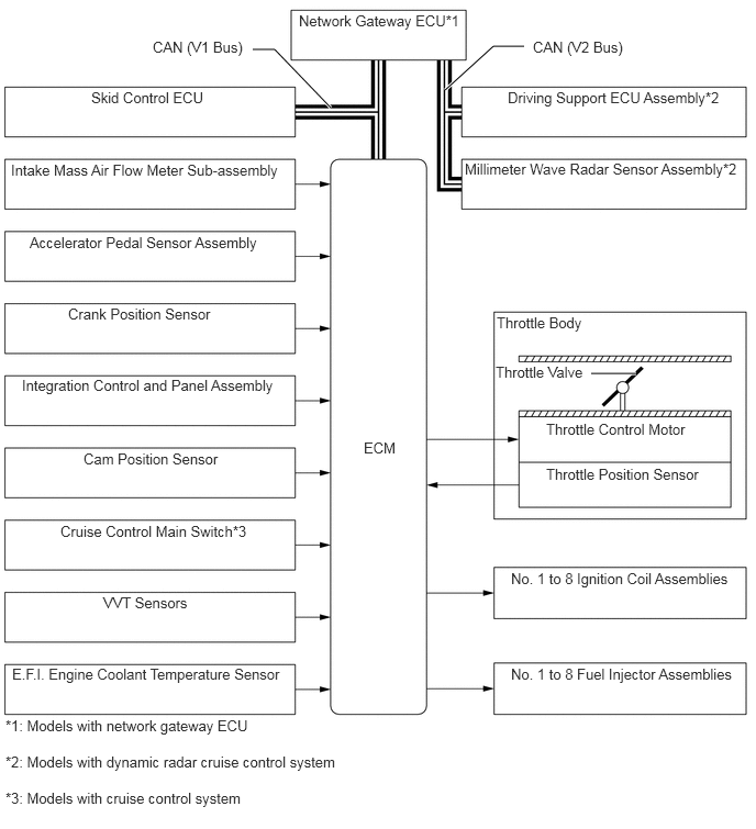
System Diagram
W133413E01
4.219,0.854 4.677,0.438 4.677,0.438 4.969,0.438 true 3.135,1.021 2.604,0.469 2.604,0.469 2.396,0.469 true 5.604,3.542 6.031,3.542 true 2.833,0.115 4.375,0.531 1.542,0.417 10 false Network Gateway ECU*1 4.813,0.844 6.99,1.26 2.177,0.417 10 false Driving Support ECU Assembly*2 4.406,1.521 7.094,1.969 2.688,0.448 10 false Millimeter Wave Radar Sensor Assembly*2 0.865,0.844 2.24,1.26 1.375,0.417 10 false Skid Control ECU 0.104,1.531 2.76,1.958 2.656,0.427 10 false Intake Mass Air Flow Meter Sub-assembly 0.281,2.219 2.75,2.635 2.469,0.417 10 false Accelerator Pedal Sensor Assembly 0.646,2.896 2.729,3.313 2.083,0.417 10 false Crank Position Sensor 0.208,3.573 2.76,4.01 2.552,0.438 10 false Integration Control and Panel Assembly 0.792,4.271 2.76,4.688 1.969,0.417 10 false Cam Position Sensor 0.573,4.958 2.76,5.396 2.188,0.438 10 false Cruise Control Main Switch*3 0.979,5.635 2.771,6.063 1.792,0.427 10 false VVT Sensors 0.115,6.313 2.76,6.75 2.646,0.438 10 false E.F.I. Engine Coolant Temperature Sensor 5.052,0.365 6.844,0.792 1.792,0.427 10 false CAN (V2 Bus) 1.448,0.365 2.417,0.781 0.969,0.417 10 false CAN (V1 Bus) 4.708,2.979 6.156,3.323 1.448,0.344 10 false Throttle Body 4.698,3.448 6.146,3.792 1.448,0.344 10 false Throttle Valve 5.177,3.99 6.885,4.344 1.708,0.354 10 false Throttle Control Motor 5.177,4.417 6.885,4.771 1.708,0.354 10 false Throttle Position Sensor 4.844,5.406 7.031,5.833 2.188,0.427 10 false No. 1 to 8 Ignition Coil Assemblies 4.844,6.313 7.031,6.74 2.188,0.427 10 false No. 1 to 8 Fuel Injector Assemblies 0.052,6.802 2.531,7.156 2.479,0.354 10 false *1: Models with network gateway ECU 0.052,7.146 3.5,7.51 3.448,0.365 10 false *2: Models with dynamic radar cruise control system 0.052,7.49 3.5,7.854 3.448,0.365 10 false *3: Models with cruise control system 3.448,4.167 3.875,4.531 0.427,0.365 10 false ECM