NEW FEATURES [2015/08 Update] NEW FEATURES GENERAL/CONTROL/DETAILS MULTIPLEX COMMUNICATION
CAN
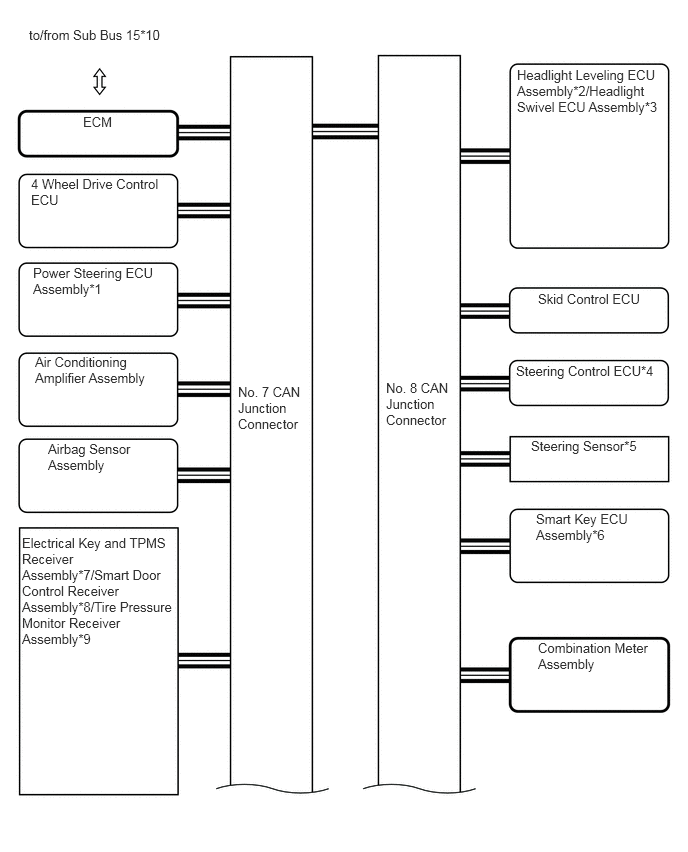
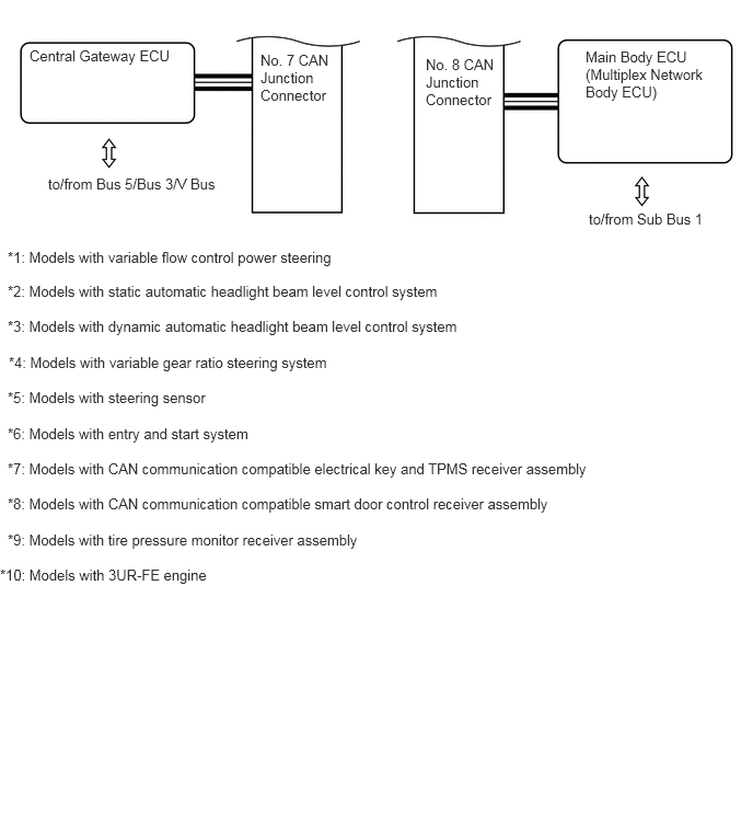
The configuration of the CAN communication system has been changed.
A central gateway ECU has been adopted and configured into the CAN communication system for collectively controlling the CAN buses.
System Diagram
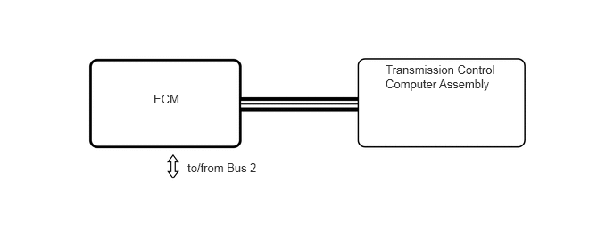
Models with Central Gateway ECU
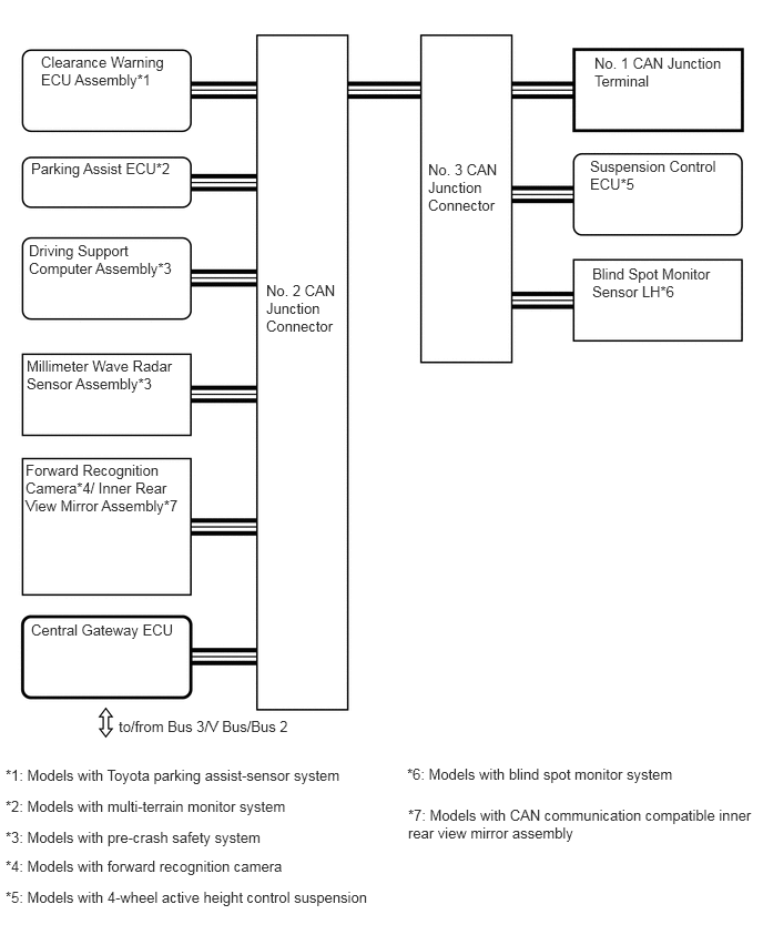
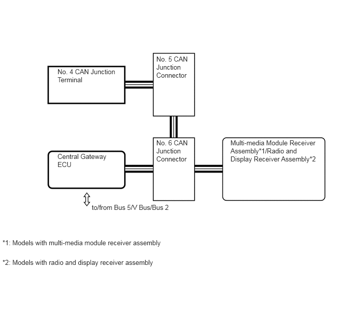
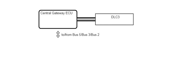
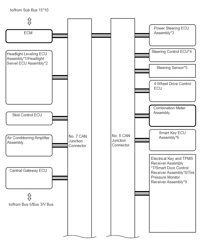
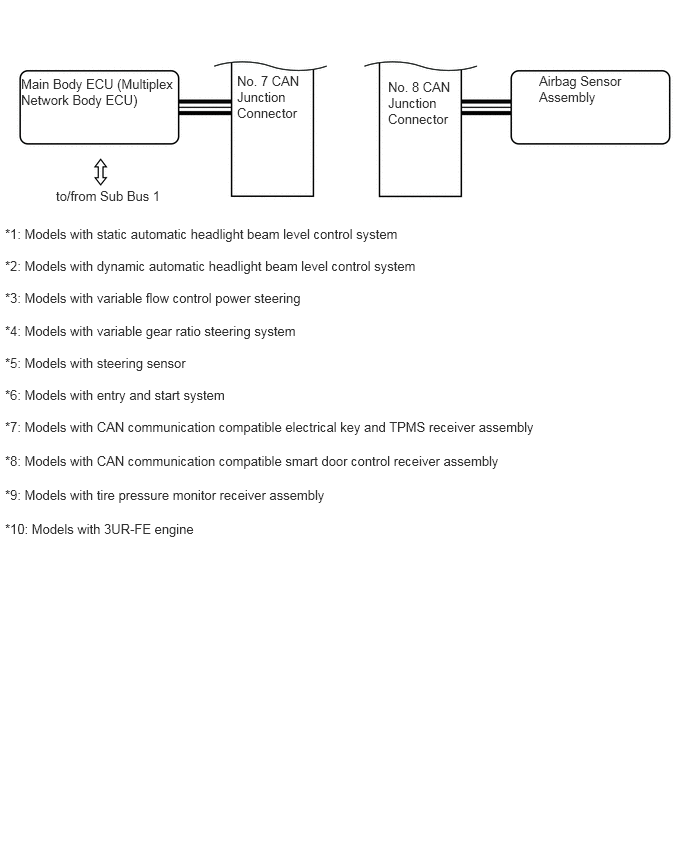
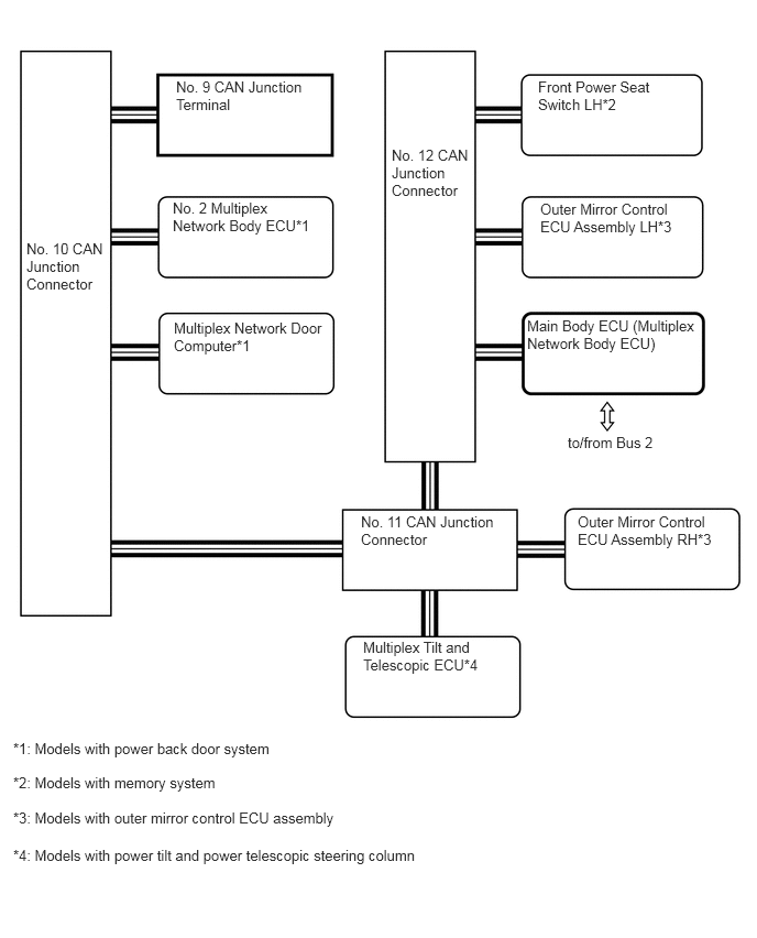
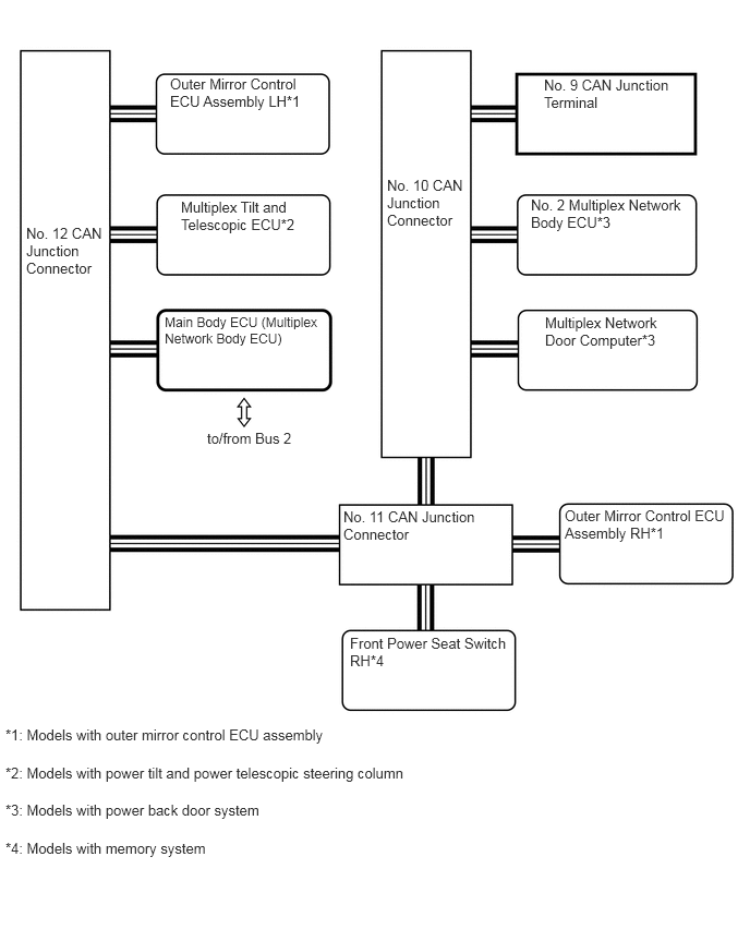
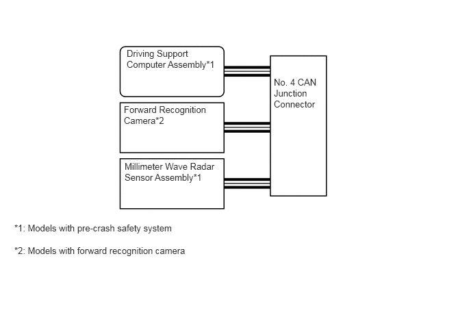
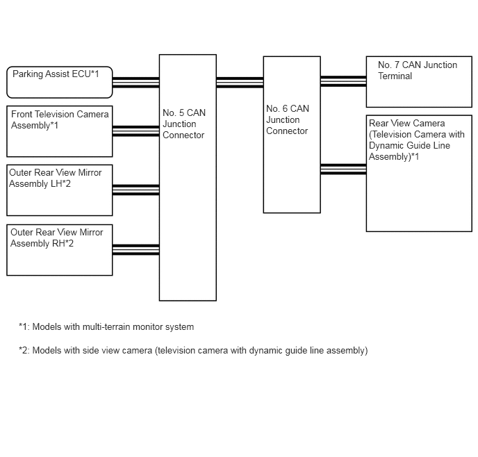
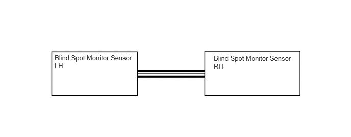
Models without Central Gateway ECU
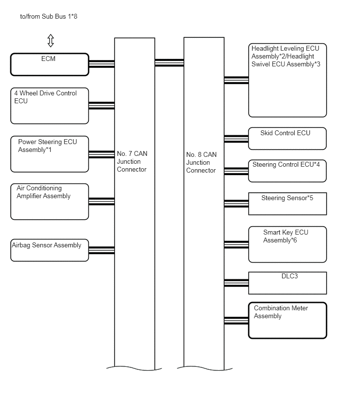
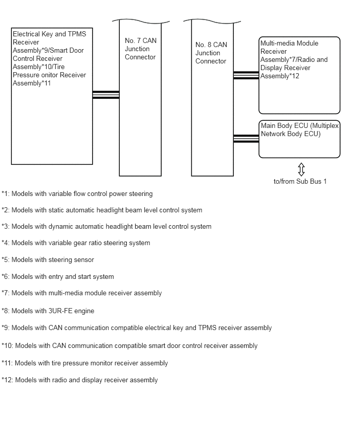
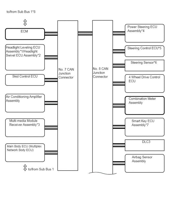
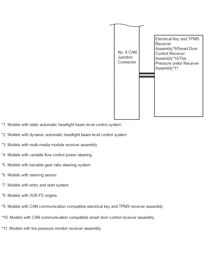
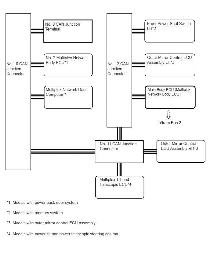
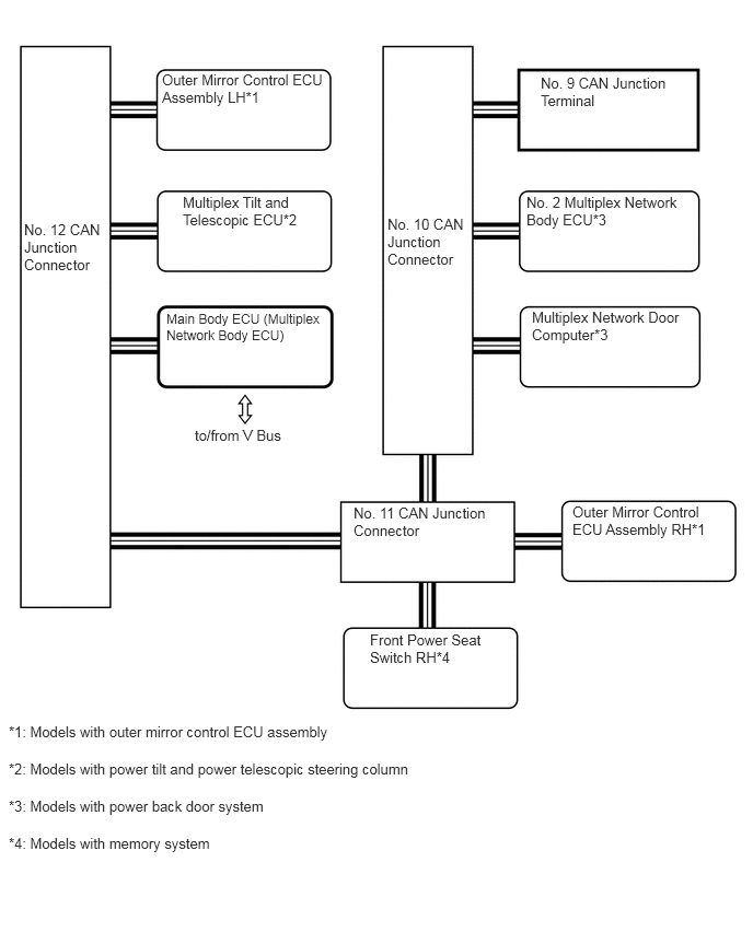
Layout of Main Components
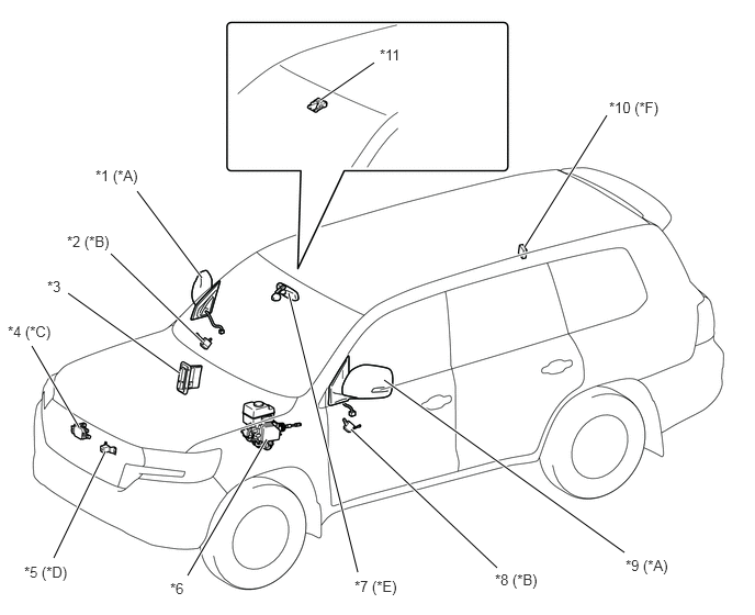
| *A | Models with Side View Camera (Television Camera with Dynamic Guide Line Assembly) | *B | Models with Outer Mirror Control ECU Assembly |
| *C | Models with Pre-crash Safety System | *D | Models with Multi-terrain Monitor System |
| *E | Models with CAN Communication Compatible Inner Rear View Mirror Assembly | *F | Models with CAN Communication Compatible Electrical Key and TPMS Receiver Assembly |
| *G | Models with Forward Recognition Camera | - | - |
| *1 | Outer Rear View Mirror Assembly RH | *2 | Outer Mirror Control ECU Assembly RH |
| *3 | ECM | *4 | Millimeter Wave Radar Sensor Assembly |
| *5 | Front Television Camera Assembly | *6 | Skid Control ECU |
| *7 | Inner Rear View Mirror Assembly | *8 | Outer Mirror Control ECU Assembly LH |
| *9 | Outer Rear View Mirror Assembly LH | *10 | Electrical Key and TPMS Receiver Assembly |
| *11 | Forward Recognition Camera | - | - |
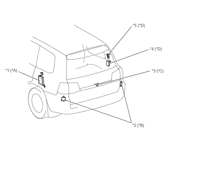
| *A | Models with 4-wheel Active Height Control Suspension | *B | Models with Blind Spot Monitor System |
| *C | Models with Multi-terrain Monitor System | *D | Models with Power Back Door System |
| *1 | Suspension Control ECU | *2 | Blind Spot Monitor Sensor |
| *3 | Rear View Camera (Television Camera with Dynamic Guide Line Assembly) | *4 | No. 2 Multiplex Network Body ECU |
| *5 | Multiplex Network Door Computer | - | - |
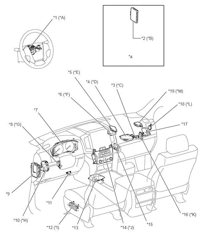
| *A | Models with Steering Sensor | *B | Models with Entry and Start System |
| *C | Models with Toyota Parking Assist-sensor System | *D | Models with Multi-terrain Monitor System |
| *E | Models with Pre-crash Safety System | *F | Models with Variable Flow Control Power Steering |
| *G | Models with Power Tilt and Power Telescopic Steering Column | *H | Models with Variable Gear Ratio Steering System |
| *I | Models with Memory System | *J | Models with Multi-media Module Receiver Assembly |
| *K | Models with 3UR-FE Engine | *L | Models with Static Automatic Headlight Beam Level Control System |
| *M | Models with Central Gateway ECU | - | - |
| *1 | Steering Sensor | *2 | Smart Key ECU Assembly |
| *3 | Clearance Warning ECU Assembly | *4 | Parking Assist ECU |
| *5 | Driving Support Computer Assembly | *6 | Power Steering ECU Assembly |
| *7 | Combination Meter Assembly | *8 | Multiplex Tilt and Telescopic ECU |
| *9 | Main Body ECU (Multiplex Network Body ECU) | *10 | Steering Control ECU |
| *11 | DLC3 | *12 | Front Power Seat Switch LH |
| *13 | Airbag Sensor Assembly | *14 | Multi-media Module Receiver Assembly |
| *15 | Air Conditioning Amplifier Assembly | *16 | Transmission Control Computer Assembly |
| *17 | 4 Wheel Drive Control ECU | *18 | Headlight Leveling ECU Assembly |
| *19 | Central Gateway ECU | - | - |
| *a | Refer to the Service Bulletin for the installation position of the part. | - | - |
LIN
Description
A LIN communication compatible refreshing seat switch*1, ECM*2, generator assembly*2, headlight swivel ECU assembly*3 and headlight leveling motor*3 have been adopted.
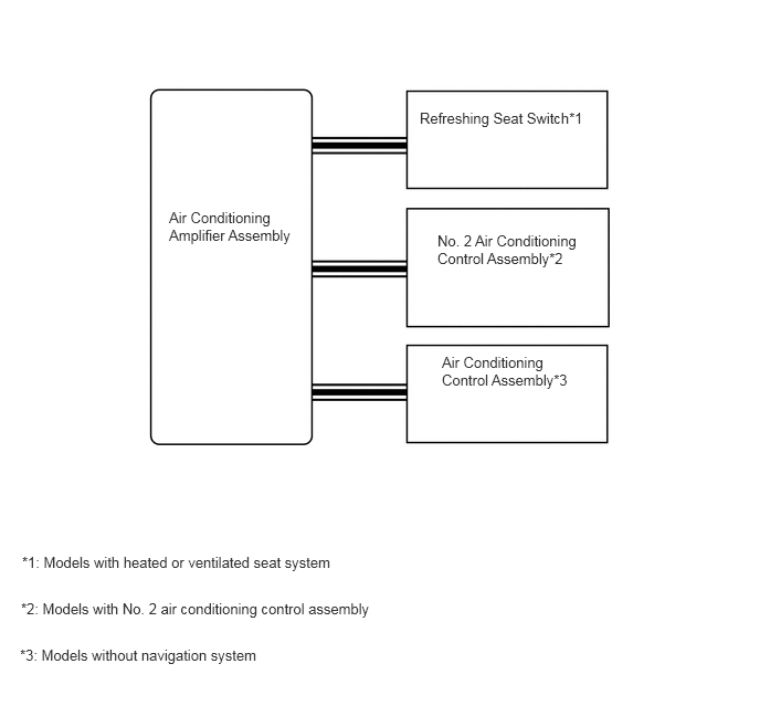
The refreshing seat switch*1 has been adopted to the configuration of the LIN communication for air conditioning system.
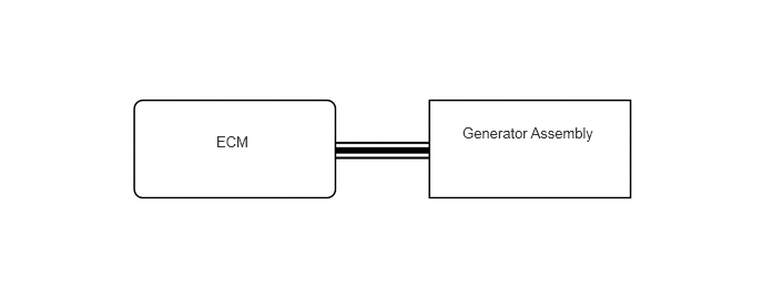
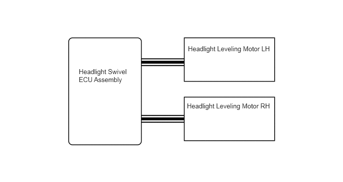
A LIN communication for charging system and dynamic automatic headlight beam level control system has been adopted.
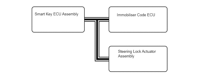
A LIN communication for steering lock system and entry and start system has been changed.*4
*1: Models with heated or ventilated seat system
*2: Models with 3UR-FE engine
*3: Models with dynamic automatic headlight beam level control system
*4: Models with entry and start system
System Diagram
Layout of Main Components
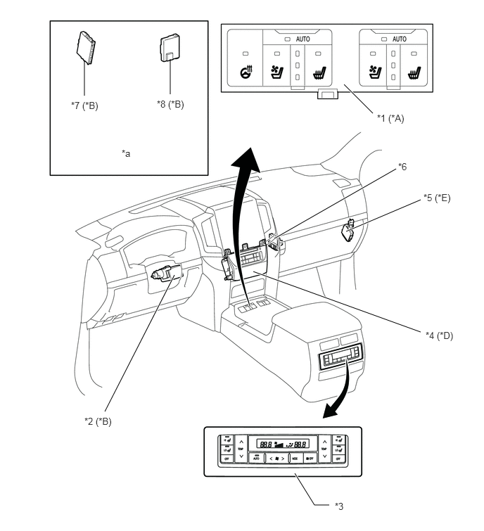
| *A | Models with Heated or Ventilated Seat System | *B | Models with No. 2 Air Conditioning Control Assembly |
| *C | Models without Navigation System | *D | Models with Entry and Start System |
| *E | Models with Dynamic Automatic Headlight Beam Level Control System | - | - |
| *1 | Refreshing Seat Switch | *2 | Steering Lock Actuator Assembly |
| *3 | No. 2 Air Conditioning Control Assembly | *4 | Air Conditioning Control Assembly |
| *5 | Headlight Swivel ECU Assembly | *6 | Air Conditioning Amplifier Assembly |
| *7 | Smart Key ECU Assembly | *8 | Immobiliser Code ECU |
| *a | Refer to the Service Bulletin for the installation position of the part. | - | - |
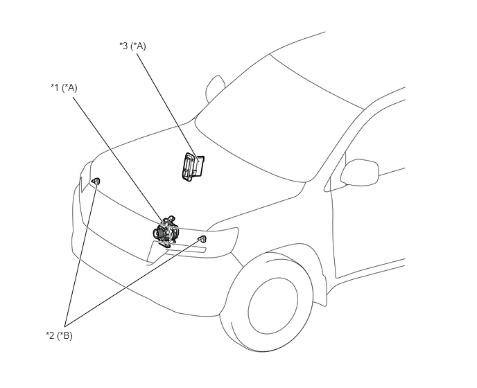
| *A | Models with 3UR-FE Engine | *B | Models with Dynamic Automatic Headlight Beam Level Control System |
| *1 | Generator Assembly | *2 | Headlight Leveling Motor |
| *3 | ECM | - | - |