Home › General › BODY ELECTRICAL › ELECTRIC POWER CONTROL SYSTEM
NM2660E _V1 General _054361 BODY ELECTRICAL _0269831 ELECTRIC POWER CONTROL SYSTEM UN GENERAL/CONTROL/DETAILS F

BODY ELECTRICAL  ELECTRIC POWER CONTROL SYSTEM  GENERAL/CONTROL/DETAILS  SYSTEM OPERATION  


SYSTEM ACTIVATION TIMING CONTROL


a.

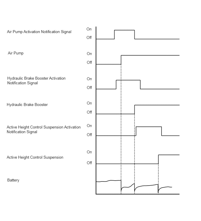
This control controls the air injection system, hydraulic brake booster and active height control suspension. It adjusts the activation timing of each system to prevent systems which use a relatively high amount of electrical power from activating simultaneously and enables those systems to activate efficiently.


b.

If the ECM receives the brake booster pump assembly activation notification signal from the skid control ECU with actuator when the engine is started, the ECM advances the activation timing of the air pump bank 1 so that the brake booster pump assembly and air pump bank 1 are not activated simultaneously.


c.

The suspension control ECU controls the height control pump & motor assembly so that the height control pump & motor assembly is not activated while activation notification signals are being received from the ECM and skid control ECU with actuator. When a predetermined time has elapsed since receiving the activation notification signals, the suspension control ECU transmits the height control pump & motor activation notification signals to the ECM and skid control ECU with actuator, and activates the height control pump & motor assembly. As a result, the activation timing of each system is appropriately controlled and power supply voltage decrease is prevented.
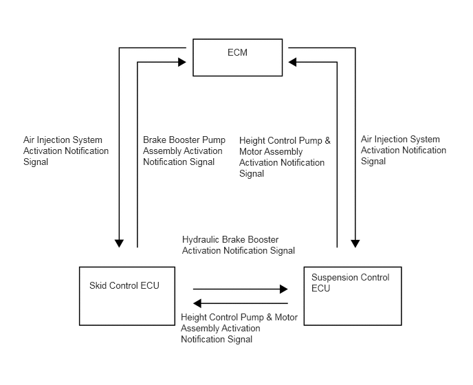
System Diagram
Y202221E01
3.448,0.708 3.948,1.063 0.5,0.354 10 false ECM 0.354,2.031 1.708,3.208 1.354,1.177 10 false Air Injection System Activation Notification Signal 2.167,2.031 3.521,3.208 1.354,1.177 10 false Brake Booster Pump Assembly Activation Notification Signal 3.625,2.042 5.073,3.458 1.448,1.417 10 false Height Control Pump & Motor Assembly Activation Notification Signal 5.469,2.021 6.802,3.135 1.333,1.115 10 false Air Injection System Activation Notification Signal 4.719,4.115 5.948,4.656 1.229,0.542 10 false Suspension Control ECU 2.74,4.719 4.563,5.792 1.823,1.073 10 false Height Control Pump & Motor Assembly Activation Notification Signal 1.354,4.24 2.469,4.708 1.115,0.469 10 false Skid Control ECU 2.76,3.542 4.552,4.271 1.792,0.729 10 false Hydraulic Brake Booster Activation Notification Signal

Timing Chart
Y202222E01
0.25,1.042 3.021,1.521 2.771,0.479 10 false Air Pump Activation Notification Signal 0.281,1.802 0.906,2.167 0.625,0.365 10 false Air Pump 0.26,2.698 2.396,3.198 2.135,0.5 10 false Hydraulic Brake Booster Activation Notification Signal 0.24,3.635 1.802,4.052 1.563,0.417 10 false Hydraulic Brake Booster 0.24,4.438 3.01,4.917 2.771,0.479 10 false Active Height Control Suspension Activation Notification Signal 0.24,5.51 3.01,5.99 2.771,0.479 10 false Active Height Control Suspension 0.26,6.323 0.771,6.729 0.51,0.406 10 false Battery 3.083,0.948 3.406,1.24 0.323,0.292 10 false On 3.083,1.25 3.406,1.542 0.323,0.292 10 false Off 3.094,1.823 3.417,2.115 0.323,0.292 10 false On 3.094,2.135 3.417,2.427 0.323,0.292 10 false Off 3.094,3.031 3.417,3.323 0.323,0.292 10 false Off 3.094,2.719 3.417,3.01 0.323,0.292 10 false On 3.094,3.583 3.417,3.875 0.323,0.292 10 false On 3.094,3.906 3.417,4.198 0.323,0.292 10 false Off 3.094,4.385 3.417,4.677 0.323,0.292 10 false On 3.094,4.708 3.417,5 0.323,0.292 10 false Off 3.094,5.323 3.417,5.615 0.323,0.292 10 false On 3.094,5.708 3.417,6 0.323,0.292 10 false Off


LOAD CONTROL


a.

When the engine is started, the ECM transmits the load control request signal to the air conditioning amplifier assembly. Upon receiving this signal, the air conditioning amplifier assembly suspends the relevant system operations for a few seconds. As a result, when coupled with the system activation timing control, this control prevents the power supply voltage from decreasing excessively when the engine is started and provides a stable power supply.
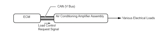
System Diagram
Y197049E02
1.969,0.792 2.229,0.302 2.229,0.302 2.469,0.302 true 1.031,0.667 1.5,0.969 0.469,0.302 10 false ECM 2.542,0.198 3.531,0.51 0.99,0.313 10 false CAN (V Bus) 1.688,1.052 2.667,1.74 0.979,0.688 10 false Load Control Request Signal 2.469,0.635 4.76,0.969 2.292,0.333 10 false Air Conditioning Amplifier Assembly 5.406,0.719 7.01,1.115 1.604,0.396 10 false Various Electrical Loads