BODY ELECTRICAL POWER BACK DOOR SYSTEM GENERAL/CONTROL/DETAILS CONSTRUCTION AND OPERATION
POWER BACK DOOR UNIT ASSEMBLY
Rotation of the power back door motor moves the arm forward and back via the gears, link mechanism and slider mechanism. The back door is opened and closed by movement of this arm.
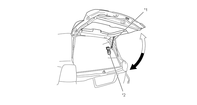
| *1 | Arm | *2 | Power Back Door Unit Assembly |
BACK DOOR With CLOSER LOCK ASSEMBLY
General
The back door with closer lock assembly consists of 3 position detection switches (neutral position switch, half latch switch, and back door courtesy switch), sector gear, open lever, latch, and opener & closer motor.
The rotation of the opener & closer motor is transmitted to the close or open lever via the sector gear. The operation of the open or closer lever engages or releases the latch.
When this system does not operate due to a discharged battery or other malfunctions, the back door can be opened by directly operating the open lever in the back door with closer lock assembly.
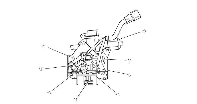
| *1 | Open Lever | *2 | Sector Gear |
| *3 | Close Lever | *4 | Latch |
| *5 | Half Latch Switch and Back Door Courtesy Switch | *6 | Latch Lever |
| *7 | Neutral Position Switch | *8 | Opener & Closer Motor |
Opener Operation
When the opener & closer motor rotates clockwise, the sector gear, which links the opener & closer motor via the gear, moves to the left. This makes the sector gear push the open lever to the left. As a result, the ratchet moves in the releasing direction to release the latch.
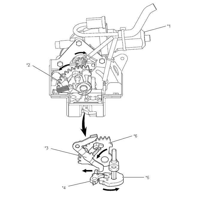
| *1 | Opener & Closer Motor | *2 | Sector Gear |
| *3 | Open Lever | *4 | Ratchet |
| *5 | Latch | *6 | Sector Gear |
Closer Operation
When the opener & closer motor rotates counterclockwise, the sector gear, which links the opener & closer motor via the gear, moves to the right. This makes the projection A, which is mounted on the closer lever that moves in conjunction with the sector gear, push the latch lever to the right. As a result, the latch moves in the engaging direction.
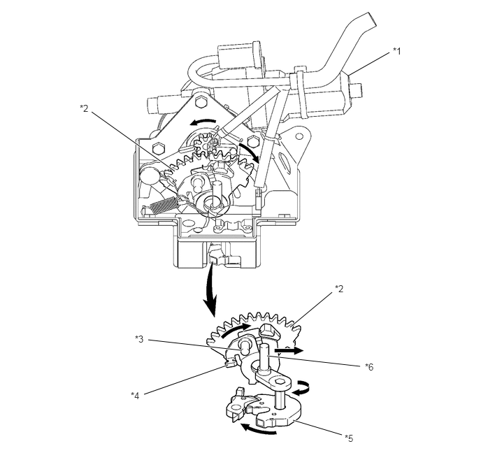
| *1 | Opener & Closer Motor | *2 | Sector Gear |
| *3 | Projection A | *4 | Close Lever |
| *5 | Latch | *6 | Latch Lever |
TOUCH SENSOR
While the back door is moving in the closing direction, if one of the touch sensors located on each side of the back door becomes compressed due to the jamming of a foreign object, the built-in pieces of conductive rubber contact each other, causing the resistance of the sensor to change and a current to flow. Accordingly, the power back door ECU determines that the back door has jammed.
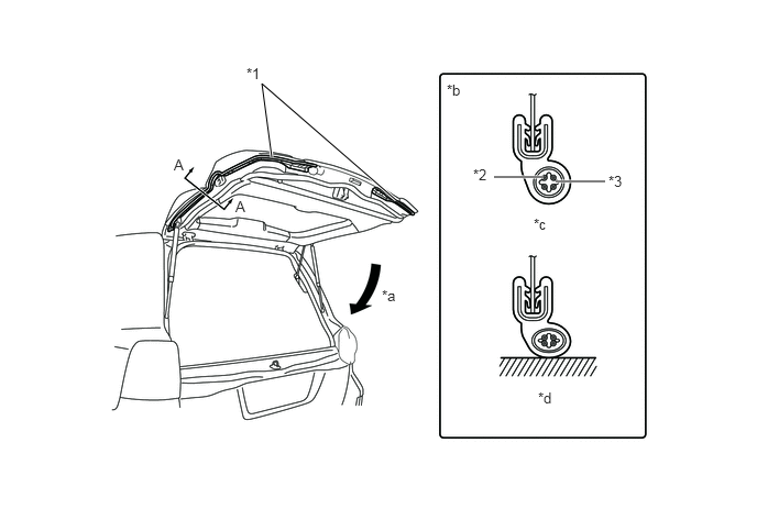
| *1 | Touch Sensor | *2 | Core Wire |
| *3 | Conductive Rubber | - | - |
| *a | Back Door Close Direction | *b | A - A Cross Section |
| *c | Normal Condition | *d | Compressed Condition |