Home › General › BODY ELECTRICAL › MULTIPLEX COMMUNICATION
NM2660E _V1 General _054361 BODY ELECTRICAL _0272099 MULTIPLEX COMMUNICATION UN GENERAL/CONTROL/DETAILS F

BODY ELECTRICAL  MULTIPLEX COMMUNICATION  GENERAL/CONTROL/DETAILS  CAN  


GENERAL


a.

The Controller Area Network (CAN) is a serial data communication network for real time application. It is a multiplex communication network equipped in a vehicle, and has communication speeds of 500 kbps (HS-CAN) and 250 kbps (MS-CAN), and the ability to detect malfunctions.


b.

The HS-CAN consists of the V Bus and Movement Control Bus.*

*: Models with movement control Bus


c.

The MS-CAN consists of the MS Bus.


d.

The network gateway ECU has a gateway function and is used to transmit data between the V bus and Movement Control Bus*.

*: Models with network gateway ECU


e.

The main body ECU has a gateway function and is used to transmit data between the V Bus and MS Bus.


f.

The CAN has 2 terminating resistors which are necessary for accurate judgment of communication on the main bus.


g.

The communication wire used is a twisted-pair wire. The bus line has a high line (2.5 V to 3.5 V of voltage is applied) and a low line (1.5 V to 2.5 V of voltage is applied).


SYSTEM DIAGRAM


a.

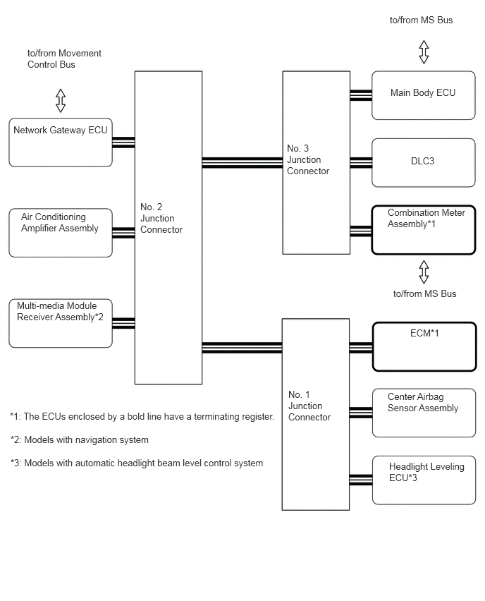
Models with Network Gateway ECU

V Bus (LHD Models)
Y202123E01
0.406,0.698 1.552,1.156 1.146,0.458 10 false to/from Movement Control Bus 0.198,1.833 1.604,2.292 1.406,0.458 10 false Network Gateway ECU 0.313,3.115 1.521,3.573 1.208,0.458 10 false Air Conditioning Amplifier Assembly 2.073,2.969 2.917,3.563 0.844,0.594 10 false No. 2 Junction Connector 4.24,2.104 5.083,2.698 0.844,0.594 10 false No. 3 Junction Connector 4.26,5.74 5.104,6.333 0.844,0.594 10 false No. 1 Junction Connector 5.771,1.281 6.896,1.49 1.125,0.208 10 false Main Body ECU 5.76,0.208 6.958,0.427 1.198,0.219 10 false to/from MS Bus 6.073,2.292 6.635,2.479 0.563,0.188 10 false DLC3 6.063,4.833 6.625,5.021 0.563,0.188 10 false ECM*1 5.729,5.771 6.896,6.219 1.167,0.448 10 false Center Airbag Sensor Assembly 5.729,3.052 6.938,3.51 1.208,0.458 10 false Combination Meter Assembly*1 0.146,6.063 4.781,6.271 4.635,0.208 10 false *1: The ECUs enclosed by a bold line have a terminating register. 0.156,6.406 4.792,6.615 4.635,0.208 10 false *2: Models with navigation system 0.25,4.427 1.667,4.958 1.417,0.531 10 false Multi-media Module Receiver Assembly*2 5.75,6.802 6.917,7.25 1.167,0.448 10 false Headlight Leveling ECU*3 5.813,4.25 7.01,4.469 1.198,0.219 10 false to/from MS Bus 0.156,6.75 4.844,7.188 4.688,0.438 10 false *3: Models with automatic headlight beam level control system

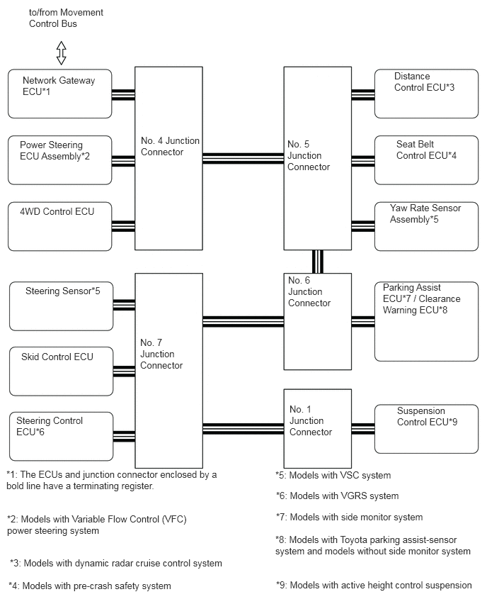
Movement Control Bus (LHD Models)
Y202124E01
0.427,0.094 1.583,0.479 1.156,0.385 10 false to/from Movement Control Bus 0.333,1.094 1.531,1.5 1.198,0.406 10 false Network Gateway ECU*1 0.292,3.021 1.521,3.406 1.229,0.385 10 false 4WD Control ECU 0.375,4.188 1.479,4.563 1.104,0.375 10 false Steering Sensor*5 0.313,5.156 1.51,5.531 1.198,0.375 10 false Skid Control ECU 5.833,2.031 6.781,2.406 0.948,0.375 10 false Seat Belt Control ECU*4 5.74,2.969 6.885,3.333 1.146,0.365 10 false Yaw Rate Sensor Assembly*5 5.635,4.135 6.948,4.729 1.313,0.594 10 false Parking Assist ECU*7 / Clearance Warning ECU*8 5.844,5.948 6.813,6.333 0.969,0.385 10 false Suspension Control ECU*9 0.24,6.094 1.594,6.448 1.354,0.354 10 false Steering Control ECU*6 2.073,1.979 2.938,2.573 0.865,0.594 10 false No. 4 Junction Connector 4.229,2.031 5.083,2.635 0.854,0.604 10 false No. 5 Junction Connector 4.24,4.031 5.083,4.646 0.844,0.615 10 false No. 6 Junction Connector 2.063,4.948 2.885,5.656 0.823,0.708 10 false No. 7 Junction Connector 4.26,5.927 5.094,6.594 0.833,0.667 10 false No. 1 Junction Connector 0.094,6.885 3.208,7.563 3.115,0.677 10 false *1: The ECUs and junction connector enclosed by a bold line have a terminating register. 0.104,7.542 3.094,8.188 2.99,0.646 10 false *2: Models with Variable Flow Control (VFC) power steering system 4.063,7.51 6.458,7.854 2.396,0.344 10 false *7: Models with side monitor system 4.052,7.844 7.01,8.531 2.958,0.688 10 false *8: Models with Toyota parking assist-sensor system and models without side monitor system 0.292,2.042 1.49,2.448 1.198,0.406 10 false Power Steering ECU Assembly*2 5.802,1.031 6.75,1.406 0.948,0.375 10 false Distance Control ECU*3 0.146,8.188 3.406,8.51 3.26,0.323 10 false *3: Models with dynamic radar cruise control system 0.125,8.521 2.573,8.854 2.448,0.333 10 false *4: Models with pre-crash safety system 4.052,6.896 6.552,7.188 2.5,0.292 10 false *5: Models with VSC system 4.063,7.198 6.74,7.521 2.677,0.323 10 false *6: Models with VGRS system 4.063,8.51 7.031,8.854 2.969,0.344 10 false *9: Models with active height control suspension

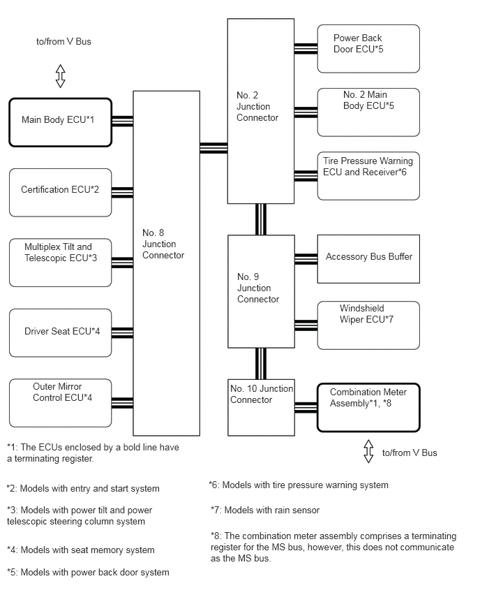
MS Bus (LHD Models)
Y202125E01
0.542,0.531 1.552,0.729 1.01,0.198 10 false to/from V Bus 0.323,1.698 1.542,1.906 1.219,0.208 10 false Main Body ECU*1 0.313,2.74 1.531,2.948 1.219,0.208 10 false Certification ECU*2 0.365,4.854 1.583,5.063 1.219,0.208 10 false Driver Seat ECU*4 0.49,5.677 1.479,6.094 0.99,0.417 10 false Outer Mirror Control ECU*4 0.365,3.594 1.5,4.021 1.135,0.427 10 false Multiplex Tilt and Telescopic ECU*3 5.073,4.51 6.01,4.927 0.938,0.417 10 false Windshield Wiper ECU*7 4.927,5.76 6.156,6.188 1.229,0.427 10 false Combination Meter Assembly*1, *8 2.125,3.385 2.917,4.01 0.792,0.625 10 false No. 8 Junction Connector 3.542,4.042 4.396,4.677 0.854,0.635 10 false No. 9 Junction Connector 3.438,5.708 4.448,6.365 1.01,0.656 10 false No. 10 Junction Connector 0.104,6.583 2.771,7.271 2.667,0.688 10 false *1: The ECUs enclosed by a bold line have a terminating register. 3.146,7.906 6.885,8.688 3.74,0.781 10 false *8: The combination meter assembly comprises a terminating register for the MS bus, however, this does not communicate as the MS bus. 5.708,6.667 6.719,6.865 1.01,0.198 10 false to/from V Bus 3.531,1.333 4.385,1.969 0.854,0.635 10 false No. 2 Junction Connector 4.979,0.479 5.917,0.896 0.938,0.417 10 false Power Back Door ECU*5 5.125,1.323 6.063,1.74 0.938,0.417 10 false No. 2 Main Body ECU*5 4.865,3.74 6.333,4.25 1.469,0.51 10 false Accessory Bus Buffer 4.823,2.313 6.292,2.802 1.469,0.49 10 false Tire Pressure Warning ECU and Receiver*6 0.094,7.198 2.5,7.542 2.406,0.344 10 false *2: Models with entry and start system 0.104,7.521 2.573,8.167 2.469,0.646 10 false *3: Models with power tilt and power telescopic steering column system 0.104,8.115 2.417,8.448 2.313,0.333 10 false *4: Models with seat memory system 0.104,8.448 2.698,8.792 2.594,0.344 10 false *5: Models with power back door system 3.115,7.146 6.354,7.396 3.24,0.25 10 false *6: Models with tire pressure warning system 3.146,7.521 5.542,7.698 2.396,0.177 10 false *7: Models with rain sensor


b.

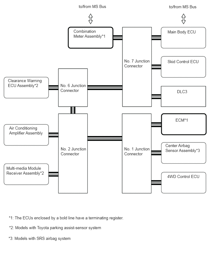
Models without Network Gateway ECU
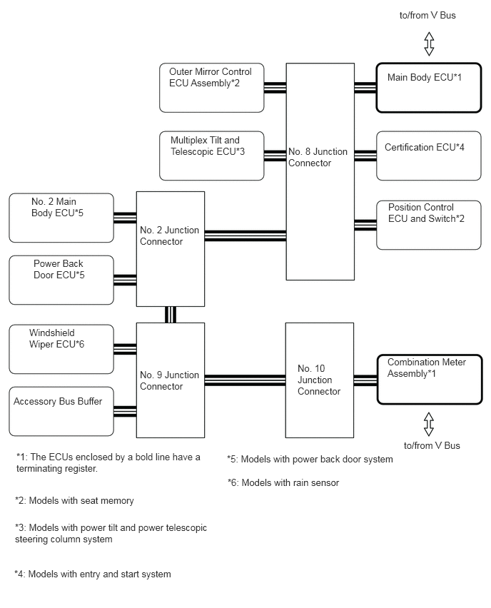
V Bus (LHD Models)
Y202388E01
2.688,0.135 3.844,0.333 1.156,0.198 10 false to/from MS Bus 5.771,0.146 6.927,0.344 1.156,0.198 10 false to/from MS Bus 5.719,1 6.875,1.198 1.156,0.198 10 false Main Body ECU 5.719,2.01 6.875,2.208 1.156,0.198 10 false Skid Control ECU 6.042,3.031 6.76,3.198 0.719,0.167 10 false DLC3 5.99,4 6.708,4.167 0.719,0.167 10 false ECM*1 2.51,0.979 3.635,1.354 1.125,0.375 10 false Combination Meter Assembly*1 0.271,2.656 1.542,3.063 1.271,0.406 10 false Clearance Warning ECU Assembly*2 0.313,4.271 1.583,4.677 1.271,0.406 10 false Air Conditioning Amplifier Assembly 0.219,5.635 1.594,6.094 1.375,0.458 10 false Multi-media Module Receiver Assembly*2 5.646,4.865 6.917,5.271 1.271,0.406 10 false Center Airbag Sensor Assembly*3 5.708,5.917 6.865,6.115 1.156,0.198 10 false 4WD Control ECU 4.24,4.979 5.115,5.729 0.875,0.75 10 false No. 1 Junction Connector 0.302,7.323 5.271,7.542 4.969,0.219 10 false *1: The ECUs enclosed by a bold line have a terminating register. 0.313,7.656 5.281,7.875 4.969,0.219 10 false *2: Models with Toyota parking assist-sensor system 2.073,4.979 2.948,5.729 0.875,0.75 10 false No. 2 Junction Connector 2.063,2.823 2.938,3.573 0.875,0.75 10 false No. 6 Junction Connector 4.24,1.99 5.115,2.74 0.875,0.75 10 false No. 7 Junction Connector 0.292,8.021 5.26,8.24 4.969,0.219 10 false *3: Models with SRS airbag system

MS Bus (LHD Models)
Y202389E01
5.833,0.135 6.896,0.344 1.063,0.208 10 false to/from V Bus 5.896,6.417 6.958,6.625 1.063,0.208 10 false to/from V Bus 5.656,1.042 6.896,1.25 1.24,0.208 10 false Main Body ECU*1 5.615,2.063 6.854,2.271 1.24,0.208 10 false Certification ECU*4 0.24,6.583 2.938,7.177 2.698,0.594 10 false *1: The ECUs enclosed by a bold line have a terminating register. 0.219,7.219 3.323,7.625 3.104,0.406 10 false *2: Models with seat memory 0.198,5.771 1.615,5.969 1.417,0.198 10 false Accessory Bus Buffer 0.427,4.771 1.344,5.208 0.917,0.438 10 false Windshield Wiper ECU*6 0.49,3.76 1.323,4.146 0.833,0.385 10 false Power Back Door ECU*5 0.458,2.854 1.313,3.25 0.854,0.396 10 false No. 2 Main Body ECU*5 5.656,5.198 6.927,5.635 1.271,0.438 10 false Combination Meter Assembly*1 5.667,2.938 6.938,3.375 1.271,0.438 10 false Position Control ECU and Switch*2 2.469,0.958 3.74,1.396 1.271,0.438 10 false Outer Mirror Control ECU Assembly*2 2.49,1.958 3.76,2.396 1.271,0.438 10 false Multiplex Tilt and Telescopic ECU*3 4.208,2.125 5.115,2.917 0.906,0.792 10 false No. 8 Junction Connector 4.344,5.292 5.25,6.083 0.906,0.792 10 false No. 10 Junction Connector 2.042,3.271 2.948,4.063 0.906,0.792 10 false No. 2 Junction Connector 2.042,5.385 2.948,6.177 0.906,0.792 10 false No. 9 Junction Connector 0.219,7.615 3.406,8.042 3.188,0.427 10 false *3: Models with power tilt and power telescopic steering column system 0.208,8.292 5.354,8.521 5.146,0.229 10 false *4: Models with entry and start system 3.313,6.615 6.448,7.198 3.135,0.583 10 false *5: Models with power back door system 3.323,6.958 7.135,7.438 3.813,0.479 10 false *6: Models with rain sensor


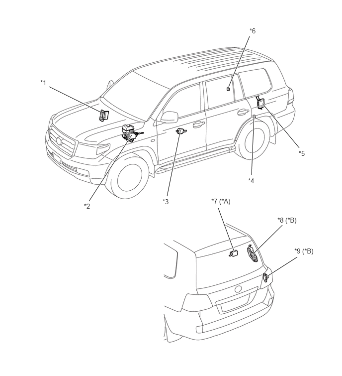
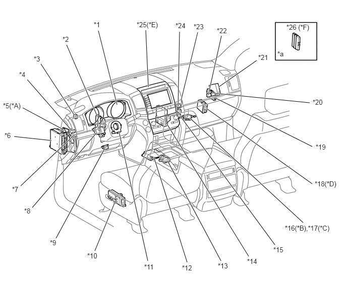
LAYOUT OF MAIN COMPONENTS


Y202126C01
2.104,2.344 1.031,1.813 true 1.865,4.208 2.76,2.823 true 3.5,4.104 3.781,2.719 true 4.792,1.813 5.229,0.76 true 5.271,3.656 5.323,2.396 true 6.271,3.094 5.5,2.167 true 4.906,5.26 4.573,4.354 true 5.313,5.302 5.917,4.708 true 5.594,5.781 6.229,5.375 true 0.844,1.646 1,1.844 0.156,0.198 10 false *1 1.76,4.229 1.917,4.427 0.156,0.198 10 false *2 3.406,4.135 3.563,4.333 0.156,0.198 10 false *3 5.198,3.698 5.354,3.896 0.156,0.198 10 false *4 6.26,3.125 6.417,3.323 0.156,0.198 10 false *5 5.229,0.563 5.385,0.76 0.156,0.198 10 false *6 4.427,4.125 4.833,4.417 0.406,0.292 10 false *7 (*A) 5.813,4.521 6.219,4.813 0.406,0.292 10 false *8 (*B) 6.167,5.167 6.573,5.458 0.406,0.292 10 false *9 (*B)
*A Models with Tire Pressure Warning System *B Models with Power Back Door System
*1 ECM *2 Hydraulic Brake Booster Assembly
·

Skid Control ECU


*3 Outer Mirror ECU *4 No. 1 Junction Connector
*5 Suspension Control ECU *6 No. 9 Junction Connector
*7 Tire Pressure Warning ECU and Receiver *8 Power Back Door ECU
*9 No. 2 Main Body ECU - -


Y202127C01
0.667,4.292 2,2.74 true 0.427,3.844 1.521,2.802 true 1.156,4.927 2.167,3.063 true 1.958,5.188 2.375,4.177 true 4.51,1.802 5.302,1.25 true 3.74,2.073 4.083,0.667 true 3.677,2.177 3.708,0.656 true 3.063,1.802 3.01,0.625 true 2.417,2.167 2.031,0.635 true 2,2.385 1.375,0.927 true 1.531,2.375 0.844,1.323 true 3.052,5.396 2.458,2.729 true 3.865,5.427 3.177,3.25 true 5.135,5.302 3.427,2.531 true 5.677,5.063 3.719,2.396 true 6.26,4.604 3.917,2.438 true 6.448,3.802 4.26,2.24 true 6.448,3.031 4.458,2.031 true 6.396,2.125 4.417,1.927 true 0.292,2.823 1.063,2.906 true 0.469,2.229 1.302,2.677 true 0.563,1.646 1.479,2.698 true 4.302,1.958 4.573,0.74 true 4.563,5.396 3.458,3.323 true 1.292,0.729 1.615,0.927 0.323,0.198 10 false *2 0.698,1.135 1.021,1.333 0.323,0.198 10 false *3 0.396,1.458 0.719,1.656 0.323,0.198 10 false *4 0.094,2.719 0.417,2.917 0.323,0.198 10 false *6 0.25,3.833 0.573,4.031 0.323,0.198 10 false *7 0.5,4.281 0.823,4.479 0.323,0.198 10 false *8 1.031,4.938 1.354,5.135 0.323,0.198 10 false *9 1.938,0.427 2.26,0.625 0.323,0.198 10 false *1 1.802,5.208 2.125,5.406 0.323,0.198 10 false *10 2.979,5.438 3.302,5.635 0.323,0.198 10 false *11 3.76,5.458 4.083,5.656 0.323,0.198 10 false *12 4.5,5.417 4.823,5.615 0.323,0.198 10 false *13 5.104,5.323 5.427,5.521 0.323,0.198 10 false *14 5.646,5.083 5.969,5.281 0.323,0.198 10 false *15 6.521,2.958 6.844,3.156 0.323,0.198 10 false *19 6.458,2.031 6.781,2.229 0.323,0.198 10 false *20 3.625,0.448 3.948,0.646 0.323,0.198 10 false *24 4,0.469 4.323,0.667 0.323,0.198 10 false *23 4.479,0.552 4.802,0.75 0.323,0.198 10 false *22 5.917,0.479 6.417,0.708 0.5,0.229 10 false *26 (*F) 5.333,1.104 5.656,1.302 0.323,0.198 10 false *21 0.063,2.104 0.594,2.302 0.531,0.198 10 false *5(*A) 2.823,0.427 3.354,0.625 0.531,0.198 10 false *25(*E) 6.5,3.719 7.031,3.917 0.531,0.198 10 false *18(*D) 5.885,4.635 7,4.854 1.115,0.219 10 false *16(*B),*17(*C) 5.729,1.031 6.052,1.229 0.323,0.198 10 false *a
*A Models with VGRS System *B Models with Toyota Parking Assist-sensor System and Models without Side Monitor System
*C Models with Parking Assist Monitor System *D Models with Rain Sensor
*E Models with Navigation System *F Models with Entry and Start System
*1 Combination Meter Assembly *2 Seat Belt Control ECU
*3 No. 7 Junction Connector *4 No. 3 Junction Connector
*5 Steering Control ECU *6 Main Body ECU (Driver Side Junction Block)
*7 No. 8 Junction Connector *8 Multiplex Tilt and Telescopic ECU
*9 DLC3 *10 Driver Seat ECU
*11 Steering Sensor *12 Center Airbag Sensor Assembly
*13 Yaw Rate Sensor Assembly *14 Air Conditioning Amplifier Assembly
*15 No. 11 Junction Connector *16 Clearance Warning ECU
*17 Parking Assist ECU *18 Windshield Wiper ECU
*19 Network Gateway ECU *20 No. 4 Junction Connector
*21 4WD Control ECU *22 No. 10 Junction Connector
*23 No. 2 Junction Connector *24 No. 5 Junction Connector
*25 Multi-media Module Receiver Assembly *26 Certification ECU
*a Refer to the Service Bulletin for the installation of the part. - -


DIAGNOSIS


a.

If a malfunction occurs on the CAN communication line, the ECU that is connected to the CAN communication line stores the DTC (Diagnostic Trouble Code) in its memory.


b.

For details, refer to the Repair Manual