Home › General › NEW FEATURES [2018/08 Update] › NEW FEATURES › from 2018.08
NM2660E _V1 General _074678 NEW FEATURES [2018/08 Update] _0362911 NEW FEATURES UN GENERAL/CONTROL/DETAILS F

NEW FEATURES [2018/08 Update]  NEW FEATURES  GENERAL/CONTROL/DETAILS  AC60F AUTOMATIC TRANSMISSION  


OUTLINE


a.

Optitron display type combination meter assembly has been adopted depending on the specifications for vehicles equipped with AC60F automatic transmission.


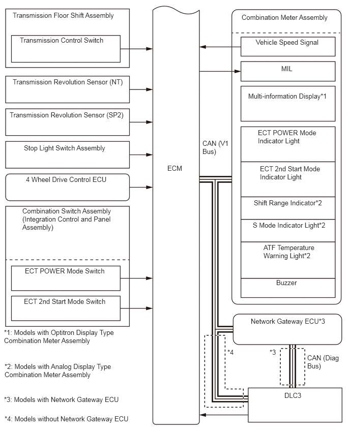
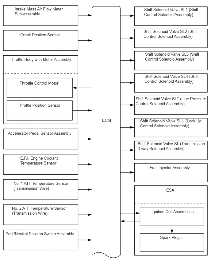
SYSTEM DIAGRAM

X137623E01
0.5,0.219 2.219,0.865 1.719,0.646 10 false Intake Mass Air Flow Meter Sub-assembly 0.688,1.094 2.083,1.625 1.396,0.531 10 false Crank Position Sensor 0.333,1.927 2.51,2.375 2.177,0.448 10 false Throttle Body with Motor Assembly 0.667,2.729 2.021,3.198 1.354,0.469 10 false Throttle Control Motor 0.604,3.479 2.115,3.948 1.51,0.469 10 false Throttle Position Sensor 0.271,4.427 2.521,4.927 2.25,0.5 10 false Accelerator Pedal Sensor Assembly 0.688,5.271 2.115,5.927 1.427,0.656 10 false E.F.I. Engine Coolant Temperature Sensor 0.458,6.125 2.406,6.781 1.948,0.656 10 false No. 1 ATF Temperature Sensor (Transmission Wire) 0.406,6.969 2.354,7.625 1.948,0.656 10 false No. 2 ATF Temperature Sensor (Transmission Wire) 0.188,7.833 2.604,8.281 2.417,0.448 10 false Park/Neutral Position Switch Assembly 3.469,3.99 3.844,4.333 0.375,0.344 10 false ECM 4.896,0.24 6.813,0.875 1.917,0.635 10 false Shift Solenoid Valve SL1 (Shift Control Solenoid Assembly) 4.875,0.979 6.792,1.656 1.917,0.677 10 false Shift Solenoid Valve SL2 (Shift Control Solenoid Assembly) 4.927,1.75 6.833,2.438 1.906,0.688 10 false Shift Solenoid Valve SL3 (Shift Control Solenoid Assembly) 4.906,2.5 6.781,3.188 1.875,0.688 10 false Shift Solenoid Valve SL4 (Shift Control Solenoid Assembly) 4.604,3.26 7.01,3.948 2.406,0.688 10 false Shift Solenoid Valve SLT (Line Pressure Control Solenoid Assembly) 4.76,4.01 6.917,4.667 2.156,0.656 10 false Shift Solenoid Valve SLU (Lock Up Control Solenoid Assembly) 4.677,4.781 7,5.479 2.323,0.698 10 false Shift Solenoid Valve SL (Transmission 3-way Solenoid Assembly) 5.646,6.354 6,6.74 0.354,0.385 10 false ESA 5.146,7.083 6.646,7.552 1.5,0.469 10 false Ignition Coil Assemblies 5.438,7.958 6.24,8.458 0.802,0.5 10 false Spark Plugs 5.083,5.594 6.771,6.094 1.688,0.5 10 false Fuel Injector Assembly

X140739E01
0.26,0.229 2.635,0.688 2.375,0.458 10 false Transmission Floor Shift Assembly 0.198,2.271 2.552,2.74 2.354,0.469 10 false Transmission Revolution Sensor (SP2) 0.49,2.948 2.302,3.396 1.813,0.448 10 false Stop Light Switch Assembly 0.531,3.594 2.208,4.052 1.677,0.458 10 false 4 Wheel Drive Control ECU 0.458,4.24 2.354,5.271 1.896,1.031 10 false Combination Switch Assembly (Integration Control and Panel Assembly) 0.51,5.469 2.208,5.906 1.698,0.438 10 false ECT POWER Mode Switch 0.49,6.094 2.26,6.542 1.771,0.448 10 false ECT 2nd Start Mode Switch 3.427,3.365 3.813,3.75 0.385,0.385 10 false ECM 4.948,0.271 6.802,0.708 1.854,0.438 10 false Combination Meter Assembly 5.24,0.781 6.615,1.115 1.375,0.333 10 false Vehicle Speed Signal 5.76,1.323 6.146,1.615 0.385,0.292 10 false MIL 5.281,2.635 6.542,3.281 1.26,0.646 10 false ECT POWER Mode Indicator Light 5.323,3.375 6.594,3.99 1.271,0.615 10 false ECT 2nd Start Mode Indicator Light 5.198,4.073 6.719,4.469 1.521,0.396 10 false Shift Range Indicator*2 5.177,4.531 6.719,4.927 1.542,0.396 10 false S Mode Indicator Light*2 5.396,4.99 6.469,5.698 1.073,0.708 10 false ATF Temperature Warning Light*2 5.656,5.708 6.146,6.083 0.49,0.375 10 false Buzzer 5.823,8.021 6.198,8.521 0.375,0.5 10 false DLC3 0.406,0.74 2.385,1.188 1.979,0.448 10 false Transmission Control Switch 0.26,1.594 2.615,2.031 2.354,0.438 10 false Transmission Revolution Sensor (NT) 5.135,6.5 6.813,7 1.677,0.5 10 false Network Gateway ECU*3 4.656,7.135 5.021,7.417 0.365,0.281 10 false *4 6.292,7.25 7,7.927 0.708,0.677 10 false CAN (Diag Bus) 5.521,7.135 5.885,7.417 0.365,0.281 10 false *3 0.094,8.5 2.823,8.833 2.729,0.333 10 false *4: Models without Network Gateway ECU 0.083,8.104 2.563,8.458 2.479,0.354 10 false *3: Models with Network Gateway ECU 5.083,1.885 6.771,2.333 1.688,0.448 10 false Multi-information Display*1 0.083,6.729 2.385,7.396 2.302,0.667 10 false *1: Models with Optitron Display Type Combination Meter Assembly 0.094,7.427 2.344,8.073 2.25,0.646 10 false *2: Models with Analog Display Type Combination Meter Assembly 4.146,2.854 4.708,3.594 0.563,0.74 10 false CAN (V1 Bus)


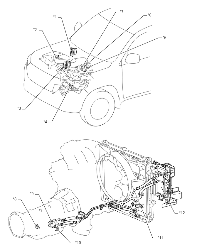
PARTS LOCATION


X137625C01
2.521,1.792 2.177,0.625 2.177,0.625 2.063,0.625 true 1.979,2.031 1.49,1.073 1.49,1.073 1.375,1.073 true 2.271,2.333 0.896,3.875 0.896,3.875 0.781,3.875 true 2.51,3.031 1.833,4.333 1.833,4.333 1.698,4.333 true 3.156,2.375 5.625,1.344 5.625,1.344 5.75,1.344 true 3.01,2.344 5.094,0.552 5.094,0.552 5.219,0.552 true 2.906,2.396 4.104,0.427 4.104,0.427 4.229,0.427 true 1.292,8.042 0.75,7.094 0.75,7.094 0.635,7.094 true 1.875,7.969 1.375,6.906 1.375,6.906 1.25,6.906 true 2.031,8.125 2.5,8.625 2.5,8.625 2.625,8.625 true 5.156,7.771 5.417,8.448 5.417,8.448 5.542,8.448 true 5.719,6.635 6.198,7.573 6.198,7.573 6.323,7.573 true 1.885,0.51 2.073,0.688 0.188,0.177 10 false *1 1.177,0.969 1.344,1.167 0.167,0.198 10 false *2 0.615,3.76 0.927,3.917 0.313,0.156 10 false *3 1.542,4.24 1.854,4.396 0.313,0.156 10 false *4 5.771,1.25 6.083,1.406 0.313,0.156 10 false *5 5.24,0.448 5.552,0.604 0.313,0.156 10 false *6 4.25,0.333 4.563,0.49 0.313,0.156 10 false *7 0.458,6.979 0.771,7.135 0.313,0.156 10 false *8 1.063,6.792 1.375,6.948 0.313,0.156 10 false *9 2.667,8.531 3.135,8.688 0.469,0.156 10 false *10 5.594,8.354 6.063,8.51 0.469,0.156 10 false *11 6.354,7.469 6.823,7.625 0.469,0.156 10 false *12
*1 ECM *2 Intake Mass Air Flow Meter Sub-assembly
*3 Throttle Body with Motor Assembly
·

Throttle Control Motor

·

Throttle Position Sensor


*4 Crank Position Sensor
*5 Ignition Coil Assemblies *6 E.F.I. Engine Coolant Temperature Sensor
*7 Fuel Injector Assemblies *8 No. 1 ATF Temperature Sensor (Transmission Wire)
*9 Park/Neutral Position Switch Assembly *10 No. 2 ATF Temperature Sensor (Transmission Wire)
*11 Water Cooled Oil Cooler (Built-In Radiator) *12 Air Cooled Oil Cooler (Oil Cooler with Hose Assembly)


X137626C01
3.969,1.802 4.229,0.552 4.229,0.552 4.354,0.552 true 3.365,2.5 2.833,0.698 2.833,0.698 2.677,0.698 true 3.219,3.292 2.104,4.271 2.104,4.271 1.948,4.271 true 3.427,3.323 2.698,4.406 2.698,4.406 2.542,4.406 true 3.594,3.302 3.229,4.5 3.229,4.5 3.073,4.5 true 3.74,3.281 4.063,4.49 4.063,4.49 4.188,4.49 true 3.958,3.167 4.688,4.417 4.688,4.417 4.813,4.417 true 4.125,3.146 5.281,4.24 5.281,4.24 5.406,4.24 true 4.188,3.042 5.771,3.906 5.771,3.906 5.896,3.906 true 4.396,0.448 4.708,0.604 0.313,0.156 10 false *1 2.5,0.594 2.677,0.771 0.177,0.177 10 false *2 1.771,4.156 1.938,4.313 0.167,0.156 10 false *3 2.365,4.281 2.552,4.469 0.188,0.188 10 false *4 2.917,4.385 3.125,4.552 0.208,0.167 10 false *5 4.208,4.385 4.521,4.542 0.313,0.156 10 false *6 4.844,4.281 5.156,4.438 0.313,0.156 10 false *7 5.448,4.125 5.76,4.281 0.313,0.156 10 false *8 5.927,3.781 6.24,3.938 0.313,0.156 10 false *9
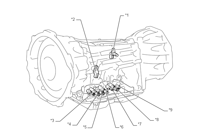
*1 Transmission Revolution Sensor (SP2) *2 Transmission Revolution Sensor (NT)
*3 Shift Solenoid Valve SLT (Line Pressure Control Solenoid Assembly) *4 Shift Solenoid Valve SL2 (Shift Control Solenoid Assembly)
*5 Shift Solenoid Valve SL1 (Shift Control Solenoid Assembly) *6 Shift Solenoid Valve SL3 (Shift Control Solenoid Assembly)
*7 Shift Solenoid Valve SLU (Lock Up Control Solenoid Assembly) *8 Shift Solenoid Valve SL4 (Shift Control Solenoid Assembly)
*9 Shift Solenoid Valve SL (Transmission 3-way Solenoid Assembly) - -


X140742C01
3.802,1.531 3.563,1.927 3.563,1.927 3.406,1.927 true 5.667,1.573 5.979,1.833 5.979,1.833 6.104,1.833 true 3.656,0.896 4.125,0.219 4.125,0.219 4.25,0.219 true 2.25,7.021 1.229,8.5 1.229,8.5 1.073,8.5 true 2.531,7.083 2.688,8.5 2.688,8.5 2.813,8.5 true 4.406,7.677 4.188,8.531 4.188,8.531 4.031,8.531 true 4.781,7.406 6.448,8.167 6.448,8.167 6.573,8.167 true 5.542,5.771 6.427,6.625 6.427,6.625 6.552,6.625 true 5.563,1.458 6.031,1.083 6.031,1.083 6.156,1.083 true 5.573,1.323 5.802,0.448 5.802,0.448 5.927,0.448 true 1.823,1.583 1.563,2.073 1.563,2.073 1.406,2.073 true 5.438,5.417 5.198,4.604 5.198,4.604 5.063,4.604 true 2.844,7.167 3.167,8.167 3.167,8.167 3.292,8.167 true 3.667,2.5 3.958,2.01 3.958,2.01 4.083,2.01 true 4.458,3.229 5.385,2.208 5.385,2.208 5.51,2.208 true 4.604,3.385 5.063,3.938 5.063,3.938 5.188,3.938 true 4.417,3.354 4.042,3.865 4.042,3.865 3.885,3.865 true 2.479,6.292 1.813,5.438 1.813,5.438 1.677,5.438 true 0.969,0.25 1.458,0.448 0.49,0.198 12 false *A: 1.229,1.969 1.406,2.125 0.177,0.156 10 false *a 3.25,1.844 3.417,2.031 0.167,0.188 10 false *b 6.188,1.74 6.5,1.896 0.313,0.156 10 false *c 5.969,0.354 6.281,0.51 0.313,0.156 10 false *e 4.292,0.135 4.604,0.292 0.313,0.156 10 false *f 0.906,8.406 1.219,8.563 0.313,0.156 10 false *2 2.854,8.417 3.167,8.573 0.313,0.156 10 false *3 3.354,8.083 3.823,8.24 0.469,0.156 10 false *4 3.854,8.427 4.323,8.583 0.469,0.156 10 false *5 6.625,8.083 7.094,8.24 0.469,0.156 10 false *6 6.604,6.531 7.073,6.688 0.469,0.156 10 false *7 6.219,0.99 6.531,1.146 0.313,0.156 10 false *d 4.615,4.5 5.135,4.719 0.521,0.219 10 false *8 (*C) 1.042,2.281 1.531,2.479 0.49,0.198 12 false *B: 5.24,3.854 5.417,4.01 0.177,0.156 10 false *a 3.708,3.771 4.021,3.927 0.313,0.156 10 false *d 5.573,2.115 5.844,2.333 0.271,0.219 10 false *e 4.125,1.885 4.396,2.104 0.271,0.219 10 false *g 1.5,5.333 1.813,5.49 0.313,0.156 10 false *1 0.208,8.573 0.521,8.729 0.313,0.156 10 false *h
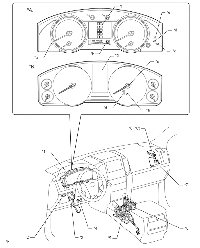
*A Models with Analog Display Type Combination Meter Assembly *B Models with Optitron Display Type Combination Meter Assembly
*C Models with Network Gateway ECU - -
*1 Combination Meter Assembly *2 Stop Light Switch Assembly
*3 Accelerator Pedal Sensor Assembly *4 DLC3
*5 Transmission Floor Shift Assembly
·

Transmission Control Switch


*6 Combination Switch Assembly (Integration Control and Panel Assembly)
·

ECT POWER Mode Switch

·

ECT 2nd Start Mode Switch


*7 4 Wheel Drive Control ECU *8 Network Gateway ECU
*a MIL *b Shift Range Indicator
*c ATF Temperature Warning Light *d ECT 2nd Start Mode Indicator Light
*e ECT POWER Mode Indicator Light *f Shift Position Indicator Light (P, R, N, D, S)
*g Multi-information Display *h The illustrations shown are examples only.


FUNCTION OF MAIN COMPONENTS


Component Function
Torque Converter Assembly
·

Transmits the engine power to the transmission.

·

Increases engine torque.


Oil Pump Assembly Provides oil pressure necessary for transmission operation.
No. 1 Clutch (C1) Connects the input shaft and the intermediate shaft.
No. 2 Clutch (C2) Connects the input shaft and the center planetary gear assembly.
No. 1 Brake (B1) Locks the rotations of the front planetary carrier and the center planetary ring gear.
No. 2 Brake (B2) Locks the rotation of the rear planetary ring gear.
No. 3 Brake (B3) Locks the rotation of the front planetary ring gear.
1-way Clutch (F) Locks the counterclockwise rotations of the center planetary carrier and the rear planetary ring gear.
Planetary Gears Change the power transmission route in accordance with clutch and brake operation, and increase or decrease output shaft revolution accordingly.
Shift Solenoid Valve SL1 (Shift Control Solenoid Assembly) Performs shift controls.
Shift Solenoid Valve SL2 (Shift Control Solenoid Assembly) Performs shift controls.
Shift Solenoid Valve SL3 (Shift Control Solenoid Assembly) Performs shift controls.
Shift Solenoid Valve SL4 (Shift Control Solenoid Assembly) Performs shift controls.
Shift Solenoid Valve SLT (Line Pressure Control Solenoid Assembly) Controls line pressure.
Shift Solenoid Valve SLU (Lock Up Control Solenoid Assembly)
·

Performs lock-up clutch controls.

·

Performs B2 brake hydraulic pressure controls (only for the 1st range when the S position is selected).


Shift Solenoid Valve SL (Transmission 3-way Solenoid Assembly) Shifts between lock-up hydraulic pressure and B2 brake hydraulic pressure.
No. 1 ATF Temperature Sensor (Transmission Wire) Detects the ATF temperature.
No. 2 ATF Temperature Sensor (Transmission Wire) Detects the ATF temperature.
Transmission Revolution Sensor (NT) Detects the input speed of the transmission.
Transmission Revolution Sensor (SP2) Detects the output speed of the transmission.
Park/Neutral Position Switch Assembly Detects the shift lever position (P, R, N, D).
Transmission Floor Shift Assembly Transmission Control Switch
·

Detects that the shift lever is in S.

·

Detects the driver's upshift and downshift operations when the shift lever is in S.


Combination Switch Assembly (Integration Control and Panel Assembly) ECT POWER Mode Switch Switches the ECT POWER mode.
ECT 2nd Start Mode Switch Switches the ECT 2nd start mode.
Stop Light Switch Assembly Detects when the brake pedal is depressed.
Combination Meter Assembly Transmits the vehicle speed signal to the ECM.
Combination Meter Assembly Shift Position Indicator Light*1 Indicates the shift position.
Shift Range Indicator*1 When S position is selected, indicates current shift range.
MIL Illuminates to inform the driver when the ECM detects a malfunction.
Multi-information Display*2
·

Displays the shift range.

·

Displays the shift position

·

Displays the drive mode.

·

Displays the message when the ATF is at a high temperature.


ECT POWER Mode Indicator Light Illuminates when the driver selects the ECT POWER mode.
ECT 2nd start Mode Indicator Light Illuminates when the driver selects the ECT 2nd start mode.
ATF Temperature Warning Light*1 Warns the driver by lighting up when the ATF is at a high temperature.
Buzzer Sounds when shift-down operation is rejected in S position.
ECM
·

Controls each solenoid valve and engine output in response to signals from each sensor and switch.

·

When the ECM detects a malfunction, it makes a diagnosis and memorizes the failed section.


4 Wheel Drive Control ECU Sends a transfer position signal to inform the ECM.

HINT:

*1: Models with analog display type combination meter assembly

*2: Models with optitron display type combination meter assembly