Home › Engine / Hybrid System › 1UR-FE (ENGINE CONTROL) › MASS AIR FLOW METER
RM2660E _51 Engine / Hybrid System _052772 1UR-FE ENGINE CONTROL _0254972 MASS AIR FLOW METER G

1UR-FE ENGINE CONTROL  MASS AIR FLOW METER  INSPECTION  


PROCEDURE

Hide 22204 1.INSPECT MASS AIR FLOW METER ASSEMBLY

a.

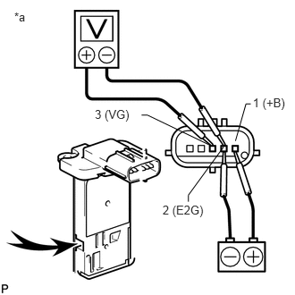
Check the output voltage.

i.
A230350E01
1.105,1.247 1.558,1.432 0.453,0.184 10 3 (VG) 0.166,0.113 0.344,0.297 0.178,0.184 10 *a 1.894,2.365 2.426,2.550 0.532,0.184 10 2 (E2G) 2.945,1.114 3.358,1.298 0.413,0.184 10 1 (+B) 2.605,1.711 2.195,2.273 2.195,2.273 2.195,2.35 false 2.743,1.642 2.866,1.21 2.866,1.21 2.921,1.21 false 2.458,1.697 1.719,1.341 1.719,1.341 1.65,1.341 false

Apply battery voltage across terminals 1 (+B) and 2 (E2G).

Text in Illustration
*a Component without harness connected
(Mass Air Flow Meter)
V100135

Air

NOTICE:

While using the battery during inspection, do not bring the positive and negative tester probes too close to each other as a short circuit may occur.


ii.

Using a voltmeter, connect the positive (+) tester probe to terminal 3 (VG) and the negative (-) tester probe to terminal 2 (E2G).


iii.

Blow air into the mass air flow meter and check that the voltage fluctuates.

If the result is not as specified, replace the mass air flow meter assembly.


b.
A230351E01
2.143,2.235 1.74,2.235 false 1.545,2.149 1.708,2.313 0.163,0.163 10 *1

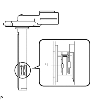
Perform a visual check for any foreign matter on the platinum hot wire (heater) of the mass air flow meter shown in the illustration.

OK:

There is no foreign matter.


Text in Illustration
*1 Platinum Hot Wire (Heater)

If the result is not as specified, replace the mass air flow meter assembly.


c.

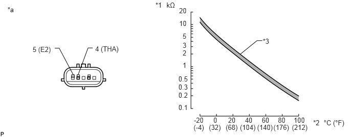
Check the intake air temperature sensor.
A231278E01
1.938,0.912 2.729,1.085 0.791,0.173 10 4 (THA) 1.588,1.533 1.792,0.98 1.792,0.98 1.886,0.98 false 1.496,1.538 1.205,0.986 1.205,0.986 1.116,0.986 false 3.647,0.132 3.858,0.308 0.211,0.177 10 20 3.647,0.397 3.862,0.584 0.215,0.187 10 10 3.718,0.655 3.860,0.832 0.142,0.177 10 5 3.718,0.846 3.848,1.008 0.129,0.162 10 3 3.718,1 3.849,1.160 0.130,0.161 10 2 3.718,1.253 3.865,1.416 0.147,0.163 10 1 3.633,1.527 3.877,1.697 0.244,0.170 10 0.5 3.633,1.698 3.883,1.861 0.250,0.163 10 0.3 3.633,1.868 3.917,2.034 0.284,0.166 10 0.2 3.633,2.114 3.872,2.277 0.239,0.163 10 0.1 3.947,2.379 4.263,2.563 0.316,0.184 10 -20 4.345,2.379 4.466,2.521 0.121,0.142 10 0 4.644,2.379 4.856,2.549 0.211,0.170 10 20 4.988,2.379 5.193,2.542 0.205,0.163 10 40 5.33,2.379 5.562,2.549 0.232,0.170 10 60 5.659,2.379 5.860,2.538 0.201,0.159 10 80 5.979,2.379 6.260,2.552 0.281,0.173 10 100 3.941,2.524 4.203,2.703 0.262,0.179 10 (-4) 4.252,2.524 4.547,2.703 0.295,0.179 10 (32) 4.595,2.524 4.889,2.703 0.295,0.179 10 (68) 4.885,2.524 5.272,2.703 0.387,0.179 10 (104) 5.235,2.524 5.623,2.703 0.387,0.179 10 (140) 5.567,2.524 5.954,2.703 0.387,0.179 10 (176) 5.943,2.524 6.331,2.703 0.387,0.179 10 (212) 5.35,0.762 5.533,0.925 0.183,0.163 10 *3 5.339,0.831 5.232,0.831 5.232,0.831 4.884,1.114 false 3.166,0.016 3.352,0.206 0.187,0.190 10 *1 3.39,0.016 3.628,0.206 0.238,0.190 10 kΩ 6.591,2.427 7.104,2.617 0.513,0.190 10 °C (°F) 6.377,2.427 6.577,2.613 0.200,0.186 10 *2 0.153,0.112 0.377,0.337 0.225,0.225 10 *a 1.79,1.531 1.84,1.58 0.049,0.049 0.664,0.924 1.092,1.075 0.428,0.151 10 5 (E2) 1.457,1.529 1.514,1.586 0.057,0.058 1.569,1.529 1.621,1.581 0.052,0.052

Text in Illustration
*1 Resistance *2 Temperature
*3 Acceptable Range - -
*a Component without harness connected
(Mass Air Flow Meter)
- -

i.

Measure the resistance according to the value(s) in the table below.

Standard Resistance:
Tester Connection Condition Specified Condition
4 (THA) - 5 (E2) -20°C (-4°F) 12.5 to 16.9 kΩ
4 (THA) - 5 (E2) 20°C (68°F) 2.19 to 2.67 kΩ
4 (THA) - 5 (E2) 60°C (140°F) 0.50 to 0.68 kΩ


If the result is not as specified, replace the mass air flow meter assembly.