RM2660E
_51
Engine / Hybrid System
_052775
3UR-FE ENGINE CONTROL
_0255022
MASS AIR FLOW METER
G
3UR-FE ENGINE CONTROL MASS AIR FLOW METER INSPECTION
PROCEDURE

 22204
1.INSPECT MASS AIR FLOW METER
a.
1.922,1.529 2.101,1.694
0.179,0.165
10
*1
1.312,2.466 1.838,1.625
false
1.838,1.625 1.915,1.625
false
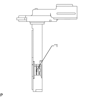
Perform a visual check for any foreign matter on the platinum hot wire (heater) of the mass air flow meter shown in the illustration.
- OK:
There is no foreign matter.
| *1 | Platinum Hot Wire (Heater) |
If the result is not as specified, replace the mass air flow meter.
b.
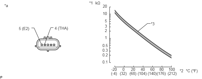
Check the intake air temperature sensor.
1.885,1.563 1.938,1.615
0.052,0.052
1.667,1.563 1.719,1.615
0.052,0.052
1.458,1.563 1.51,1.615
0.052,0.052
1.583,1.563 1.802,0.979
1.802,0.979 1.896,0.979
false
1.469,1.573 1.208,0.99
1.208,0.99 1.115,0.99
false
5.344,0.833 5.229,0.833
5.229,0.833 4.885,1.115
false
1.938,0.917 2.729,1.094
0.792,0.177
10
false
4 (THA)
3.646,0.135 3.854,0.313
0.208,0.177
10
false
20
3.646,0.396 3.865,0.583
0.219,0.188
10
false
10
3.719,0.656 3.865,0.833
0.146,0.177
10
false
5
3.719,0.844 3.844,1.01
0.125,0.167
10
false
3
3.719,1 3.844,1.156
0.125,0.156
10
false
2
3.719,1.25 3.865,1.417
0.146,0.167
10
false
1
3.635,1.531 3.875,1.698
0.24,0.167
10
false
0.5
3.635,1.698 3.885,1.865
0.25,0.167
10
false
0.3
3.635,1.865 3.917,2.031
0.281,0.167
10
false
0.2
3.635,2.115 3.875,2.281
0.24,0.167
10
false
0.1
3.948,2.375 4.26,2.563
0.313,0.188
10
false
-20
4.344,2.375 4.469,2.521
0.125,0.146
10
false
0
4.646,2.375 4.854,2.542
0.208,0.167
10
false
20
4.99,2.375 5.198,2.542
0.208,0.167
10
false
40
5.333,2.375 5.563,2.542
0.229,0.167
10
false
60
5.656,2.375 5.854,2.531
0.198,0.156
10
false
80
5.979,2.375 6.26,2.552
0.281,0.177
10
false
100
3.938,2.521 4.198,2.698
0.26,0.177
10
false
(-4)
4.25,2.521 4.542,2.698
0.292,0.177
10
false
(32)
4.594,2.521 4.885,2.698
0.292,0.177
10
false
(68)
4.885,2.521 5.271,2.698
0.385,0.177
10
false
(104)
5.24,2.521 5.625,2.698
0.385,0.177
10
false
(140)
5.563,2.521 5.948,2.698
0.385,0.177
10
false
(176)
5.948,2.521 6.333,2.698
0.385,0.177
10
false
(212)
5.354,0.76 5.542,0.927
0.188,0.167
10
false
*3
3.167,0.021 3.354,0.208
0.188,0.188
10
false
*1
3.385,0.021 3.625,0.208
0.24,0.188
10
false
kΩ
6.594,2.427 7.104,2.615
0.51,0.188
10
false
°C (°F)
6.375,2.427 6.573,2.615
0.198,0.188
10
false
*2
0.156,0.115 0.385,0.344
0.229,0.229
10
false
*a
0.667,0.927 1.094,1.073
0.427,0.146
10
false
5 (E2)
| *1 | Resistance kΩ | *2 | Temperature °C (°F) |
| *3 | Acceptable Range | - | - |
| *a | Component without harness connected
( Mass air flow meter) |
- | - |
i.
Measure the resistance according to the value(s) in the table below.
- Standard Resistance:
Tester Connection Condition Specified Condition 4 (THA) - 5 (E2) -20°C (-4°F) 12.5 to 16.9 kΩ 20°C (68°F) 2.19 to 2.67 kΩ 60°C (140°F) 0.50 to 0.68 kΩ
If the result is not as specified, replace the mass air flow meter.