RM2660E
_51
Engine / Hybrid System
_052775
3UR-FE ENGINE CONTROL
_0255027
KNOCK SENSOR
A
3UR-FE ENGINE CONTROL KNOCK SENSOR INSTALLATION
PROCEDURE

 89615
1.INSTALL KNOCK SENSOR
0.583,0.802 0.802,1.115
0.219,0.313
10
true
*A
0.729,1.135 0.938,1.344
0.208,0.208
10
true
*B
2.5,0.823 2.719,1.146
0.219,0.323
10
true
*C
2.677,1.156 2.885,1.354
0.208,0.198
10
true
*D
0.042,2.24 0.406,2.51
0.365,0.271
10
true
*A
0.042,3.427 0.25,3.625
0.208,0.198
10
false
*B
1.854,2.24 2.188,2.542
0.333,0.302
10
true
*C
1.854,3.406 2.063,3.604
0.208,0.198
10
false
*D
0.375,4.073 0.719,4.333
0.344,0.26
10
false
10°
1.438,2.917 1.781,3.177
0.344,0.26
10
false
10°
2.125,2.938 2.469,3.198
0.344,0.26
10
false
10°
3.042,4.094 3.354,4.354
0.313,0.26
10
false
10°
a.
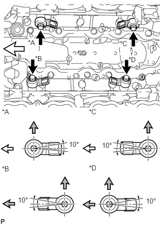
Install the 4 sensors with the 4 bolts so that the sensors are angled as shown in the illustration.
- Torque:
- 20 N*m (204 kgf*cm, 15 ft.*lbf)
- NOTICE:
-
The acceptable installation angle of the sensor is between 10° upward and downward from the horizontal position.
| *A | for Bank 2 Sensor 1 |
| *B | for Bank 1 Sensor 1 |
| *C | for Bank 2 Sensor 2 |
| *D | for Bank 1 Sensor 2 |

|
Front |

|
Upper Side |

|
Rear |
b.
Connect the 4 sensor connectors.
12611
2.INSTALL NO. 1 ENGINE COVER
12612A
3.INSTALL NO. 2 ENGINE COVER
17111
4.INSTALL INTAKE MANIFOLD