Home › Engine / Hybrid System › 1VD-FTV (ENGINE MECHANICAL) › CYLINDER BLOCK
RM2660E _51 Engine / Hybrid System _052779 1VD-FTV ENGINE MECHANICAL _0255072 CYLINDER BLOCK A

1VD-FTV ENGINE MECHANICAL  CYLINDER BLOCK  REPLACEMENT  


PROCEDURE

Hide 1.REPLACE STUD BOLT

HINT:

If a stud bolt is deformed or the threads are damaged, replace it.


a.

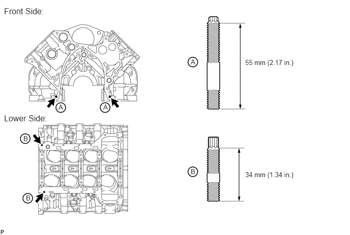
Using an E7 "TORX" wrench, replace the stud bolts labeled A shown in the illustration below.

Torque:
10 N*m (102 kgf*cm, 7 ft.*lbf)


b.

Using an E8 "TORX" wrench, replace the stud bolts labeled B shown in the illustration below.

Torque:
10 N*m (102 kgf*cm, 7 ft.*lbf)

U162903E02
5.021,1.198 6.063,1.375 1.042,0.177 10 false 55 mm (2.17 in.) 5.021,3.5 6.063,3.677 1.042,0.177 10 false 34 mm (1.34 in.) 1.198,2.115 1.354,2.281 0.156,0.167 10 false A 0.479,2.76 0.635,2.927 0.156,0.167 10 false B 0.531,3.979 0.688,4.146 0.156,0.167 10 false B 2.115,2.115 2.271,2.292 0.156,0.177 10 false A 3.906,1.188 4.063,1.354 0.156,0.167 10 false A 3.906,3.438 4.063,3.604 0.156,0.167 10 false B 0.083,0.125 1.01,0.323 0.927,0.198 12 false Front Side: 0.083,2.323 1.094,2.542 1.01,0.219 12 false Lower Side:


Hide 11434C 2.REPLACE STRAIGHT PIN

NOTICE:

It is not necessary to remove the straight pin unless it is being replaced.


a.

Remove the straight pins.


b.

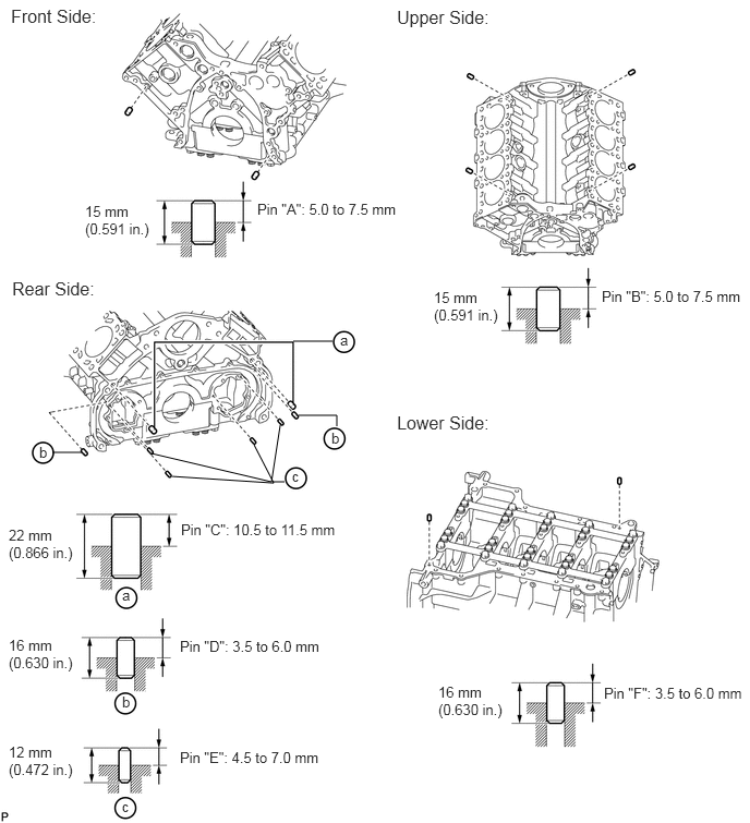
Using a plastic-faced hammer, tap in new straight pins to the cylinder block.

Standard Protrusion:
Item Specified Condition
Pin "A" and "B" 5.0 to 7.5 mm (0.197 to 0.295 in.)
Pin "C" 10.5 to 11.5 mm (0.413 to 0.453 in.)
Pin "D" and "F" 3.5 to 6.0 mm (0.138 to 0.236 in.)
Pin "E" 4.5 to 7.0 mm (0.177 to 0.276 in.)

U162902E02
2.854,3.969 3.219,3.969 3.219,3.969 3.219,4.073 false 0.5,4.323 0.781,4.323 false 1.448,4.333 2.594,4.604 2.594,4.604 2.677,4.063 false 1.646,4.552 2.615,4.615 2.615,4.615 2.427,4.25 false 2.802,3.26 3.177,3.26 false 2.604,4.604 2.719,4.604 false 0.083,5.031 0.729,5.375 0.646,0.344 10 false 22 mm (0.866 in.) 0.083,6.083 0.729,6.427 0.646,0.344 10 false 16 mm (0.630 in.) 0.083,7.104 0.75,7.458 0.667,0.354 10 false 12 mm (0.472 in.) 1.167,5.604 1.323,5.771 0.156,0.167 10 false a 1.167,6.625 1.323,6.792 0.156,0.167 10 false b 1.167,7.625 1.323,7.792 0.156,0.167 10 false c 1.729,4.979 3.281,5.135 1.552,0.156 10 false Pin "C": 10.5 to 11.5 mm 1.719,6.094 3.104,6.25 1.385,0.156 10 false Pin "D": 3.5 to 6.0 mm 1.719,7.156 3.167,7.313 1.448,0.156 10 false Pin "E": 4.5 to 7.0 mm 5.771,6.542 7.146,6.719 1.375,0.177 10 false Pin "F": 3.5 to 6.0 mm 2.458,1.917 3.958,2.073 1.5,0.156 10 false Pin "A": 5.0 to 7.5 mm 5.75,2.75 7.146,2.906 1.396,0.156 10 false Pin "B": 5.0 to 7.5 mm 4.146,2.76 4.792,3.104 0.646,0.344 10 false 15 mm (0.591 in.) 0.813,1.938 1.458,2.281 0.646,0.344 10 false 15 mm (0.591 in.) 0.115,2.656 1.021,2.854 0.906,0.198 12 false Rear Side: 0.104,0.052 1.042,0.292 0.938,0.24 12 false Front Side: 3.792,3.938 4.854,4.188 1.063,0.25 12 false Lower Side: 3.792,0.063 4.813,0.302 1.021,0.24 12 false Upper Side: 3.167,4.104 3.323,4.271 0.156,0.167 10 false b 2.792,4.469 2.948,4.635 0.156,0.167 10 false c 3.25,3.167 3.406,3.333 0.156,0.167 10 false a 0.375,4.24 0.531,4.406 0.156,0.167 10 false b 4.188,6.531 4.833,6.875 0.646,0.344 10 false 16 mm (0.630 in.)


Hide 11431A 3.REPLACE CYLINDER BLOCK TIGHT PLUG

NOTICE:

If water leaks from the tight plug or the plug corrodes, replace it.


a.

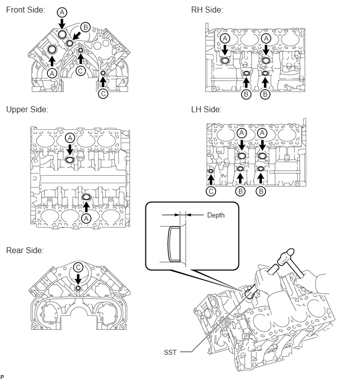
Remove the tight plugs.


b.
A132063E05
1.198,0.521 1.396,0.521 1.396,0.521 1.823,0.781 true 0.552,0.438 1.167,0.604 0.615,0.167 10 false Adhesive

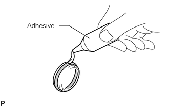
Apply adhesive around new tight plugs.

Adhesive:

Toyota Genuine Adhesive 1324, Three Bond 1324 or equivalent


c.

Using SST and a hammer, tap in the tight plugs to the specified depth.

SST
09950-60010  (09951-00180, 09951-00250, 09951-00350)
09950-70010  (09951-07150)

Standard depth:

1.7 to 2.7 mm (0.0669 to 0.106 in.)

U162901E02
5.208,6.042 3.969,7.281 3.969,7.281 3.729,7.281 true 1.406,2.771 1.563,2.938 0.156,0.167 10 false A 4.938,3.875 5.094,4.042 0.156,0.167 10 false B 5.365,3.875 5.521,4.052 0.156,0.177 10 false B 1.74,4.438 1.896,4.604 0.156,0.167 10 false A 4.615,0.708 4.771,0.875 0.156,0.167 10 false A 5.469,0.708 5.625,0.875 0.156,0.167 10 false A 1.031,1.438 1.188,1.604 0.156,0.167 10 false A 1.24,0.167 1.396,0.333 0.156,0.167 10 false A 4.958,2.656 5.115,2.823 0.156,0.167 10 false A 5.385,2.656 5.542,2.823 0.156,0.167 10 false A 5.052,1.865 5.208,2.031 0.156,0.167 10 false B 5.448,1.865 5.604,2.031 0.156,0.167 10 false B 1.729,0.479 1.885,0.646 0.156,0.167 10 false B 4.323,3.875 4.479,4.042 0.156,0.167 10 false C 2.094,1.854 2.25,2.021 0.156,0.167 10 false C 1.615,1.385 1.771,1.552 0.156,0.167 10 false C 1.573,5.448 1.729,5.615 0.156,0.167 10 false C 3.396,7.208 3.688,7.365 0.292,0.156 10 false SST 4.292,4.365 4.688,4.542 0.396,0.177 10 false Depth 0.125,0.094 0.99,0.323 0.865,0.229 12 false Front Side: 0.125,2.156 1.115,2.438 0.99,0.281 12 false Upper Side: 0.125,5.073 1.083,5.344 0.958,0.271 12 false Rear Side: 3.958,0.094 4.771,0.302 0.813,0.208 12 false RH Side: 3.958,2.156 4.75,2.417 0.792,0.26 12 false LH Side:


Hide 13411C 4.REPLACE CRANKSHAFT STRAIGHT PIN
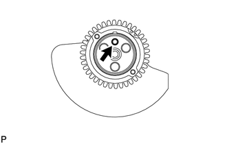
A158685

NOTICE:

It is not necessary to remove the crankshaft straight pin unless it is being replaced.


a.

Replace the pin.