Home › Engine / Hybrid System › 1VD-FTV (FUEL) › FUEL FILTER
RM2660E _51 Engine / Hybrid System _052783 1VD-FTV FUEL _0255112 FUEL FILTER A

1VD-FTV FUEL  FUEL FILTER  REPLACEMENT  


CAUTION / NOTICE / HINT

HINT:

When replacing the filter, use TOYOTA genuine parts or equivalent parts.


PROCEDURE

Hide 1.DRAIN FUEL FROM FUEL FILTER

a.

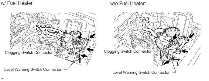
Detach the fuel hose clamp.

A176401E05
1.906,1.813 2.021,1.813 2.021,1.813 2.583,1.479 true 2.208,2.396 2.313,2.396 2.313,2.396 2.677,1.979 true 5.302,1.771 5.406,1.771 5.406,1.771 5.792,1.51 true 5.917,2.5 6.031,2.5 6.031,2.5 5.875,2.052 true 0.031,0 1.208,0.177 1.177,0.177 12 false w/ Fuel Heater: 0.167,1.729 1.865,2.271 1.698,0.542 10 true Clogging Switch Connector 0.146,2.313 2.198,2.469 2.052,0.156 10 false Level Warning Switch Connector 3.563,1.688 5.26,2.219 1.698,0.531 10 true Clogging Switch Connector 3.854,2.417 5.906,2.573 2.052,0.156 10 false Level Warning Switch Connector 3.781,0.01 5.052,0.188 1.271,0.177 12 false w/o Fuel Heater:


b.

Disconnect the clogging switch connector and level warning switch connector.

c.
A176368E04
2.479,1.063 2.313,1.063 2.313,1.063 2.146,1.563 true 1.917,2.927 2.354,2.927 false 2.49,0.99 3.323,1.313 0.833,0.323 10 true Drain Cock 2.385,2.833 3.031,2.99 0.646,0.156 10 false Container

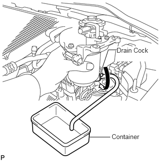
Remove the 2 nuts and lift up the fuel filter assembly.


d.

Connect a hose to the drain cock. Place the other end of the hose into a container under the drain cock.


e.

Loosen the drain cock to drain fuel.


f.

Tighten the drain cock by hand.

NOTICE:

Do not use any tools in this procedure.


g.

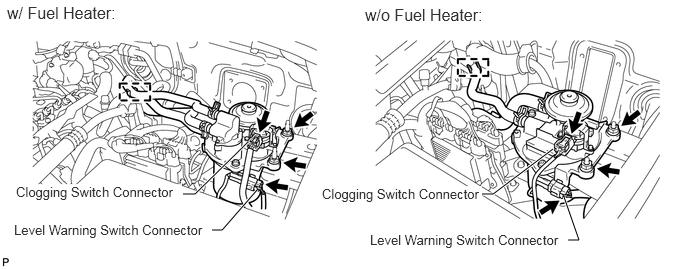
Install the fuel filter assembly with the 2 nuts.

Torque:
20 N*m (199 kgf*cm, 14 ft.*lbf)

A176401E04
1.906,2.021 2.031,2.021 2.031,2.021 2.583,1.479 true 2.208,2.396 2.313,2.396 2.313,2.396 2.677,1.979 true 5.021,2.021 5.135,2.021 5.135,2.021 5.76,1.552 true 5.917,2.5 6.031,2.5 6.031,2.5 5.875,2.052 true 0.073,0.031 1.25,0.208 1.177,0.177 12 false w/ Fuel Heater: 0.167,1.917 1.896,2.302 1.729,0.385 10 true Clogging Switch Connector 0.146,2.313 2.198,2.469 2.052,0.156 10 false Level Warning Switch Connector 3.854,2.417 5.906,2.573 2.052,0.156 10 false Level Warning Switch Connector 3.802,0.052 5.073,0.229 1.271,0.177 12 false w/o Fuel Heater: 3.354,1.938 5.021,2.323 1.667,0.385 10 true Clogging Switch Connector


h.

Connect the clogging switch connector and level warning switch connector.


i.

Attach the fuel hose clamp.


Hide 23390 2.REMOVE FUEL FILTER ELEMENT ASSEMBLY

a.

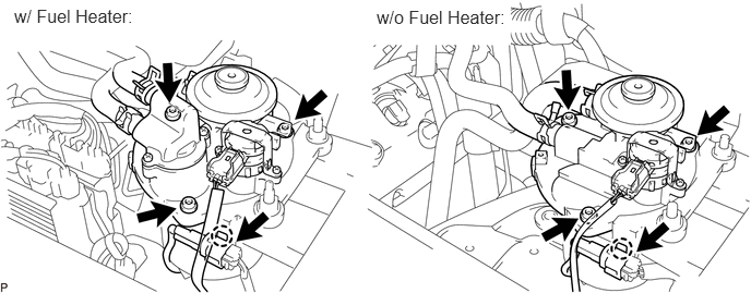
Disconnect the level warning switch connector, and detach the level warning switch connector clamp.
A384350E01
0.052,0.01 1.208,0.271 1.156,0.26 12 false w/ Fuel Heater: 3.531,0 4.875,0.427 1.344,0.427 12 true w/o Fuel Heater:


b.

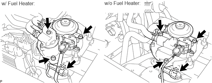
Using a 5 mm hexagon socket wrench, remove the 3 bolts and disconnect the fuel filter cap.


c.

Remove the fuel filter case and element assembly.


d.

Remove the O-ring and retainer.


e.
A163549

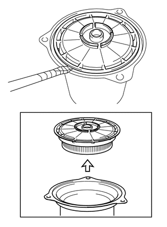
Using a screwdriver, remove the fuel filter element from the case.

NOTICE:

Do not damage the fuel filter element and case.


HINT:

Tape the screwdriver tip before use.


Hide 23390 3.INSTALL FUEL FILTER ELEMENT ASSEMBLY

a.

Clean the fuel filter case.

NOTICE:

When replacing the fuel filter, clean the fuel filter case and remove dirt completely.


b.

Install the fuel filter element to the case.
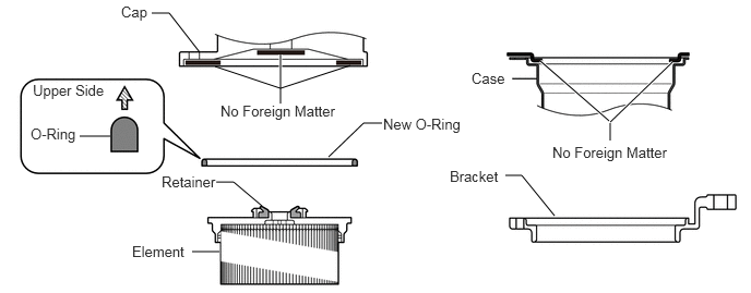
A384351E01
1.448,0.125 1.615,0.125 1.615,0.125 1.906,0.5 false 2.677,0.521 2.677,0.99 true 2.677,0.844 2.052,0.635 false 2.677,0.844 3.344,0.625 false 1.052,1.302 0.76,1.302 false 3.135,1.5 3.469,1.177 3.469,1.177 3.646,1.177 false 2.5,1.969 2.229,1.74 2.229,1.74 2.063,1.74 false 2.094,2.406 1.833,2.406 false 5.156,0.583 5.813,1.156 true 5.823,1.167 6.417,0.594 true 5.823,1.177 5.823,1.344 false 4.823,1.677 4.979,1.677 4.979,1.677 5.292,2.063 false 1.156,0.031 1.615,0.229 0.458,0.198 10 false Cap 2.104,0.979 3.333,1.167 1.229,0.188 10 false No Foreign Matter 0.313,0.781 1.115,0.979 0.802,0.198 10 false Upper Side 0.292,1.198 0.74,1.396 0.448,0.198 10 false O-Ring 3.656,1.104 4.396,1.313 0.74,0.208 10 false New O-Ring 1.542,1.656 2.073,1.833 0.531,0.177 10 false Retainer 1.26,2.323 1.823,2.5 0.563,0.177 10 false Element 4.5,0.667 4.896,0.865 0.396,0.198 10 false Case 5.271,1.375 6.438,1.552 1.167,0.177 10 false No Foreign Matter 4.292,1.604 4.833,1.792 0.542,0.188 10 false Bracket

NOTICE:

Make sure that there is no foreign matter on the areas of the case shown in the illustration.


c.

Install the retainer.


d.

Install a new O-ring.

NOTICE:

Make sure the rounded side of the O-ring faces upward as shown in the illustration.


e.

Install the fuel filter case and element assembly to the bracket.


f.

Set the fuel filter cap on the case.

NOTICE:
·

Make sure that there is no foreign matter on the areas of the cap shown in the illustration.

·

Do not turn the cap as the O-ring will be damaged.


g.

Using a 5 mm hexagon socket wrench, install the fuel filter cap with the 3 bolts.

Torque:
4.5 N*m (46 kgf*cm, 40 in.*lbf)

A384352E01
0.135,0.052 1.292,0.302 1.156,0.25 12 false w/ Fuel Heater: 3.594,0.063 4.833,0.313 1.24,0.25 12 false w/o Fuel Heater:


h.

Further tighten the first bolt tightened above so that its torque value is slightly more than the torque specification.


i.

Attach the level warning switch connector clamp and connect the level warning switch connector.


Hide 4.RESET FUEL SYSTEM WARNING LIGHT

a.
A181376

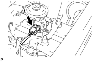
Disconnect the clogging switch connector.


b.

Turn the ignition switch to ON.


c.

After turning the ignition switch to ON, connect the clogging switch connector within 3 to 60 seconds.
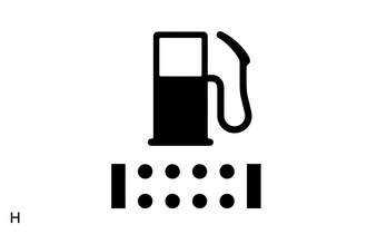

d.
A181391

w/o Multi-information Display:

Check that the fuel system warning light on the combination meter turns off.


e.

w/ Multi-information Display:

Check that the fuel system warning on the multi-information display turns off.


Hide 5.BLEED AIR FROM FUEL SYSTEM

A175110

a.

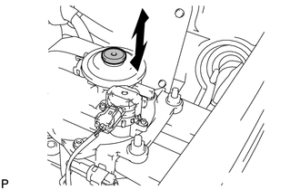
Using the hand pump, bleed air from the fuel system until pumping becomes difficult.


Hide 6.INSPECT FOR FUEL LEAK

a.

Start the engine. Check that leaking sounds, sucking sounds or other unusual sounds cannot be heard.