RM2660E
_51
Engine / Hybrid System
_052784
1GR-FE EMISSION CONTROL
_0255124
PURGE VALVE
G
1GR-FE EMISSION CONTROL PURGE VALVE INSPECTION
PROCEDURE

 25860
1.INSPECT PURGE VSV
a.
Measure the resistance according to the value(s) in the table below.
- Standard Resistance:
Tester Connection Condition Specified Condition 1 - 2 20°C (68°F) 23 to 26 Ω 1 - Body ground Always 10 MΩ or higher 2 - Body ground Always 10 MΩ or higher
- HINT:
-
When measuring the coil resistance, make sure that the surface temperature of the purge VSV is 20°C (68°F).
If the result is not as specified, replace the purge VSV.
b.
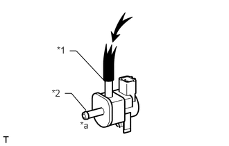
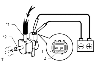
Check the operation of the purge VSV.
i.
0.853,0.667 1.026,0.841
0.173,0.173
10
*1
0.775,1.312 0.952,1.485
0.177,0.173
10
*2
1.201,1.793 1.395,1.956
0.194,0.163
10
*a
0.973,1.398 1.072,1.398
1.072,1.398 1.29,1.652
false
1.046,0.762 1.145,0.762
1.145,0.762 1.586,1.23
false
Check that air does not flow from port E to port F.
| *1 | Port E |
| *2 | Port F |
| *a | Does not flow |

|
Air pressure |
ii.
0.207,0.78 0.386,0.941
0.179,0.162
10
*1
0.103,1.218 0.282,1.380
0.179,0.162
10
*2
0.304,1.302 0.411,1.302
0.411,1.302 0.598,1.638
false
0.407,0.861 0.512,0.861
0.512,0.861 0.832,1.274
false
1.45,1.741 1.564,1.891
0.114,0.150
10
1
1.541,1.965 1.661,2.122
0.119,0.157
10
2
1.571,1.829 1.76,1.829
1.76,1.829 1.954,1.704
false
1.69,2.05 1.793,2.05
1.793,2.05 2.151,1.71
false
Apply battery voltage to the connector and check the VSV operation.
- OK:
Measurement Condition Specified Condition Battery positive (+) → Terminal 1
Battery negative (-) → Terminal 2Air flows from port E to port F
| *1 | Port E |
| *2 | Port F |
|
|
Air pressure |
If the result is not as specified, replace the purge VSV.