RM2660E
_51
Engine / Hybrid System
_052784
1GR-FE EMISSION CONTROL
_0255131
AIR SWITCHING VALVE(for Bank 2)
A
1GR-FE EMISSION CONTROL AIR SWITCHING VALVE(for Bank 2) INSTALLATION
PROCEDURE

 25702B
1.INSTALL NO. 2 EMISSION CONTROL VALVE SET
a.
Install the No. 2 emission control valve set with the 3 nuts.
- Torque:
- 21 N*m (214 kgf*cm, 15 ft.*lbf)
b.
2.418,0.056 2.598,0.219
0.180,0.163
10
*a
1.198,0.068 1.378,0.231
0.180,0.163
10
*2
3.159,0.534 3.339,0.697
0.180,0.163
10
*b
0.231,1.022 0.411,1.185
0.180,0.163
10
*1
0.433,1.108 0.499,1.108
0.499,1.108 0.661,0.746
false
1.188,0.156 1.092,0.156
1.092,0.156 0.92,0.691
false
2.938,0.82 3.187,0.971
0.250,0.151
10
60°
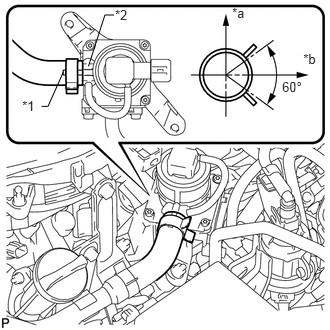
Align the paint mark with the rib and connect the No. 1 air hose.
| *1 | Paint Mark |
| *2 | Rib |
| *a | Top |
| *b | LH Side |
- HINT:
-
Make sure the direction of the hose clamp is as shown in the illustration.
c.
Connect the No. 2 emission control valve set connector.
17362
2.INSTALL NO. 2 AIR TUBE
a.
2.833,0.933 3.010,1.091
0.178,0.158
10
*1
2.999,0.084 3.176,0.242
0.178,0.158
10
*2
2.986,0.181 2.902,0.181
2.902,0.181 2.846,0.38
false
2.831,1.025 2.629,1.025
2.629,1.025 2.53,0.727
false
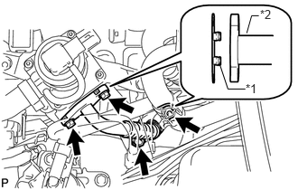
Install 2 new gaskets.
| *1 | Claw |
| *2 | No. 2 Air Tube |
- NOTICE:
-
Make sure the gasket's claws are not caught between the No. 2 emission control valve set and No. 2 air tube.
b.
Install the No. 2 air tube with the 2 bolts and 2 nuts.
- Torque:
- 10 N*m (102 kgf*cm, 7 ft.*lbf)
25860
3.INSTALL PURGE VSV
a.
Install the purge VSV (See page Engine / Hybrid System>1GR-FE (EMISSION CONTROL)>PURGE VALVE>INSTALLATION).