1UR-FE EMISSION CONTROL CANISTER(w/ Secondary Air Injection System) INSTALLATION
PROCEDURE

 77740
1.INSTALL CHARCOAL CANISTER ASSEMBLY
for Type A:
Install the vent line hose to the charcoal canister assembly, and slide the clamp to secure the hose.
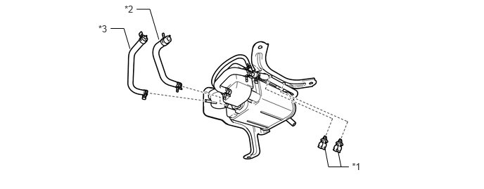
| *1 | Fuel Hose Clamp | *2 | Purge Line Hose |
| *3 | Vent Line Hose | - | - |
Install the purge line hose to the charcoal canister assembly, and slide the clamp to secure the hose.
Install the 2 fuel hose clamps to the charcoal canister assembly, and connect the hose.
Install the charcoal canister assembly with the 3 bolts.
- Torque:
- 20 N*m (199 kgf*cm, 14 ft.*lbf)
Connect the vent line hose and purge line hose to the fuel emission tube, and slide the clamp to secure the hose.
Connect the air inlet line hose to the fuel emission tube, and slide the clamp to secure the hose.
for Type B:
Install the 2 fuel hose clamps to the charcoal canister assembly.
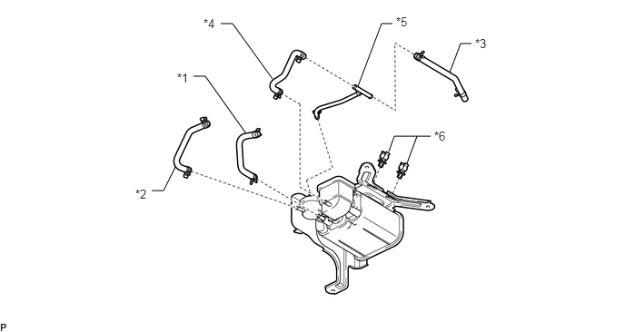
| *1 | Purge Line Hose | *2 | Vent Line Hose |
| *3 | Fuel Emission Hose A | *4 | Fuel Emission Hose B |
| *5 | Fuel Emission Hose Sub-assembly | *6 | Fuel Hose Clamp |
Install the fuel emission hose sub-assembly to the charcoal canister assembly, and slide the clamp to secure the hose.
Install the fuel emission hose B to the charcoal canister assembly and fuel emission hose subassembly, and slide the 2 clamp to secure the hose.
Install the fuel emission hose A to the fuel emission hose sub-assembly, and slide the clamp to secure the hose.
Connect the fuel emission hose A to the 2 fuel hose clamps.
Install the vent line hose to the charcoal canister assembly, and slide the clamp to secure the hose.
Install the purge line hose to the charcoal canister assembly, and slide the clamp to secure the hose.
Install the charcoal canister assembly with the 3 bolts.
- Torque:
- 20 N*m (199 kgf*cm, 14 ft.*lbf)
Connect the vent line hose and purge line hose to the 2 fuel emission tube, and slide the 2 clamps to secure the hoses.
Connect the fuel emission hose to the fuel emission tube, and slide the clamp to secure the hose.
77100U
2.INSTALL FUEL TANK SUB-ASSEMBLY (w/ Active Height Control)