1UR-FE STARTING STARTER REASSEMBLY
PROCEDURE

 28021
1.INSTALL STARTER CENTER BEARING CLUTCH SUB-ASSEMBLY
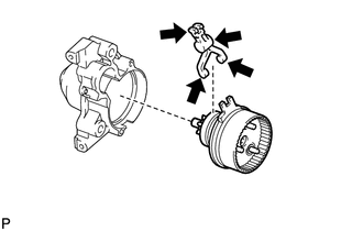
Apply high-temperature grease to the areas of the pinion drive lever indicated in the illustration.

|
High-temperature grease |
Install the pinion drive lever and rubber seal to the starter center bearing clutch.
Install the starter center bearing clutch together with the pinion drive lever and rubber seal to the starter drive housing.
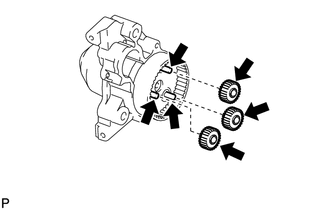
Apply high-temperature grease to the planetary gears and pins of the starter center bearing clutch as shown in the illustration.
|
|
High-temperature grease |
Install the 3 planetary gears.
28160
2.INSTALL STARTER ARMATURE ASSEMBLY
Install the starter armature to the starter yoke.
- NOTICE:
-
The magnet of the starter yoke may attract the starter armature when the starter commutator end frame is installed causing the magnet to break.
28140
3.INSTALL STARTER BRUSH HOLDER ASSEMBLY
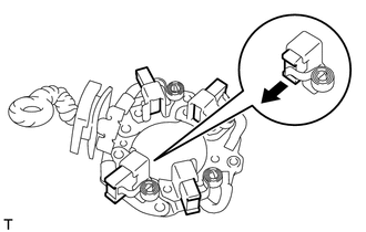
Push out the 4 brushes from the starter brush holder so that they are held in place by the springs as shown in the illustration.
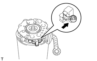
Install the starter brush holder to the starter armature and push in the 4 brushes.
- NOTICE:
-
Check that the positive (+) lead wires are not grounded.
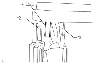
Insert the grommet between the positive side and negative side.
| *1 | Grommet |
| *2 | Negative Side |
| *3 | Positive Side |
28120
4.INSTALL STARTER YOKE ASSEMBLY
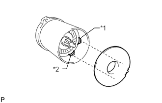
Install the starter armature plate to the starter yoke.
| *1 | Key A |
| *2 | Key B |
- NOTICE:
-
Install the starter armature plate so that the keyway is positioned between key A and key B.
Install the starter commutator end frame with the 2 screws.
- Torque:
- 1.5 N*m (15 kgf*cm, 13 in.*lbf)
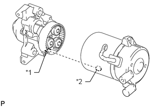
Align the key of the starter yoke with the keyway located on the starter drive housing.
| *1 | Keyway |
| *2 | Key |
Using a T25 "TORX" socket wrench, install the 2 bolts.
- Torque:
- 6.0 N*m (61 kgf*cm, 53 in.*lbf)
28150
5.INSTALL MAGNET STARTER SWITCH ASSEMBLY
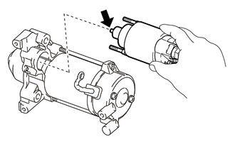
Apply high-temperature grease to the plunger hook.
|
|
High-temperature grease |
Hang the plunger of the magnet starter switch onto the pinion drive lever from the upper side.
Install the magnet starter switch with the 2 nuts.
- Torque:
- 7.5 N*m (76 kgf*cm, 66 in.*lbf)
Connect the lead wire to terminal C with the nut.
- Torque:
- 10 N*m (102 kgf*cm, 7 ft.*lbf)