RM2660E
_51
Engine / Hybrid System
_052804
CRUISE CONTROL
_0255251
DYNAMIC RADAR CRUISE CONTROL SYSTEM
J
CRUISE CONTROL DYNAMIC RADAR CRUISE CONTROL SYSTEM Distance Control ECU Power Source Circuit
DESCRIPTION
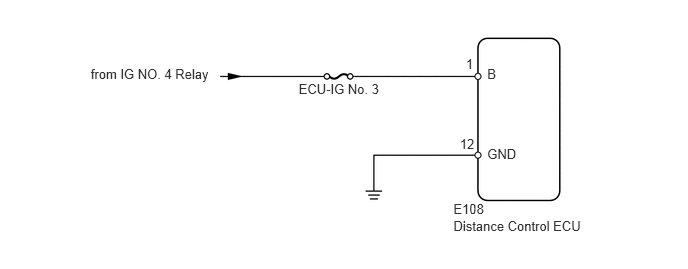
This circuit provides power to operate the distance control ECU.
WIRING DIAGRAM
0.945,0.686 2.254,0.844
1.309,0.158
10
from IG NO. 4 Relay
3.111,0.84 4.034,0.988
0.923,0.148
10
ECU-IG No. 3
4.723,2.273 6.130,2.452
1.406,0.179
10
Distance Control ECU
5.075,0.683 5.318,0.874
0.243,0.191
10
B
4.723,2.096 5.095,2.245
0.371,0.149
10
E108
4.853,0.587 4.974,0.733
0.121,0.145
10
1
5.075,1.517 5.424,1.707
0.349,0.191
10
GND
4.79,1.421 4.974,1.566
0.184,0.145
10
12
PROCEDURE
1.INSPECT FUSE (ECU-IG No. 3)
a.
Remove the ECU-IG No. 3 fuse from the cowl side junction block RH.
b.
Measure the resistance according to the value(s) in the table below.
- Standard Resistance:
Tester Connection Condition Specified Condition ECU-IG No. 3 fuse Always Below 1 Ω
OK
2.CHECK HARNESS AND CONNECTOR (DISTANCE CONTROL ECU - BATTERY AND BODY GROUND)
NG
REPLACE FUSE
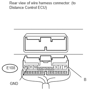
2.CHECK HARNESS AND CONNECTOR (DISTANCE CONTROL ECU - BATTERY AND BODY GROUND)
a.
2.502,2.446 2.976,2.827
false
1.026,2.47 0.718,2.935
false
0.343,0.019 2.747,0.422
2.404,0.403
10
Rear view of wire harness connector: (to Distance Control ECU)
0.361,2.968 0.799,3.126
0.438,0.158
10
GND
3.066,2.821 3.362,2.963
0.297,0.142
10
B
0.237,2.392 0.593,2.534
0.356,0.142
10
E108
Disconnect the E108 distance control ECU connector.
b.
Measure the voltage according to the value(s) in the table below.
- Standard Voltage:
Tester Connection Switch Condition Specified Condition E108-1 (B) - Body ground Engine switch on (IG) 11 to 14 V Engine switch off Below 1 V
c.
Measure the resistance according to the value(s) in the table below.
- Standard Resistance:
Tester Connection Condition Specified Condition E108-12 (GND) - Body ground Always Below 1 Ω
OK
PROCEED TO NEXT CIRCUIT INSPECTION SHOWN IN PROBLEM SYMPTOMS TABLE
(See pageEngine / Hybrid System>CRUISE CONTROL>DYNAMIC RADAR CRUISE CONTROL SYSTEM>PROBLEM SYMPTOMS TABLE)
NG
REPAIR OR REPLACE HARNESS OR CONNECTOR