AB60F AUTOMATIC TRANSMISSION / TRANSAXLE SPEED SENSOR INSTALLATION
PROCEDURE

 89413B
1.INSTALL SPEED SENSOR SP2
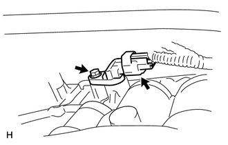
Coat a new O-ring with ATF and install it to the sensor.
Install the sensor with the bolt.
- Torque:
- 5.4 N*m (55 kgf*cm, 48 in.*lbf)
Connect the sensor connector.
89413B
2.INSTALL SPEED SENSOR NT
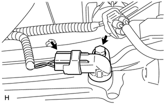
Coat a new O-ring with ATF and install it to the sensor.
Install the sensor with the bolt.
- Torque:
- 5.4 N*m (55 kgf*cm, 48 in.*lbf)
Connect the sensor connector.
17410
3.INSTALL FRONT EXHAUST PIPE ASSEMBLY (w/ DPF)
Install a new gasket and the front exhaust pipe to the monolithic converter RH with 3 new nuts.
- Torque:
- 48 N*m (489 kgf*cm, 35 ft.*lbf)
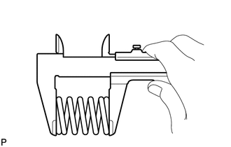
Check the free length.
Using a vernier caliper, measure the free length of the compression spring.
- Free length:
43 mm (1.69 in.)
If the free length is less than the minimum, replace the compression spring.
Install a new gasket and connect the front exhaust pipe assembly with the 2 bolts and 2 compression springs.
- Torque:
- 43 N*m (438 kgf*cm, 32 ft.*lbf)
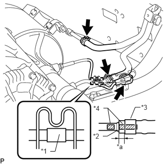
Attach the clamp and connect the exhaust gas temperature sensor connector.
| *1 | Tape |
| *2 | Stopper |
| *3 | Clip |
| *4 | Paint Mark |
| *a | 2 to 7 mm (0.0787 to 0.276 in.) |
- HINT:
-
Make sure that the tape is in the position shown in the illustration.
Install 2 new clips to the 2 air hoses.
Connect the 2 air hoses to the front exhaust pipe.
- NOTICE:
- ·
Align the paint marks of the front exhaust pipe and air hose and push on the air hose until it contacts the stopper.
·Make sure the clip is 4 to 10 mm (0.157 to 0.394 in.) from the end of the air hose when installing the clip.
·Make sure that there is no slack in the air hose, and that it is not twisted or bent.
·Take care not to damage the inner or outer surface of the air hose when installing it. If the air hose is damaged, replace it with a new one.
Connect the air fuel ratio sensor connector.
4.INSPECT FOR EXHAUST GAS LEAK