A750F AUTOMATIC TRANSMISSION / TRANSAXLE AUTOMATIC TRANSMISSION UNIT DISASSEMBLY
PROCEDURE

 35572
1.REMOVE TRANSMISSION CONTROL SHAFT LEVER RH
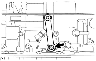
Remove the nut, spring washer and control shaft lever RH.
84540
2.REMOVE PARK/NEUTRAL POSITION SWITCH ASSEMBLY
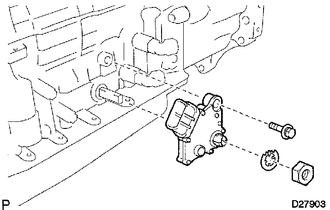
Using a screwdriver, bend the tabs of the lock washer.
Remove the nut, lock washer and bolt.
Remove the park/neutral position switch.
- HINT:
-
Make sure that the manual valve lever shaft has not been rotated prior to installing the park/neutral position switch as the detent spring may become detached from the manual valve lever shaft.
32921C
3.REMOVE OIL COOLER TUBE UNION
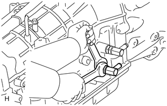
Remove the 2 oil cooler tube unions.
Remove the 2 O-rings from the oil cooler tube unions.
89413B
4.REMOVE SPEED SENSOR
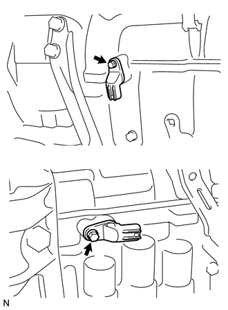
Remove the 2 bolts and 2 speed sensors.
Remove the 2 O-rings from the sensors.
35122
5.REMOVE AUTOMATIC TRANSMISSION BREATHER TUBE
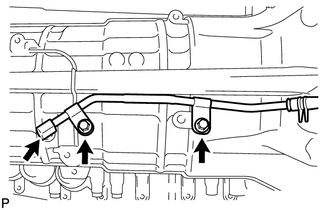
Remove the 2 bolts.
Remove the breather tube.
Remove the O-ring from the tube.
35111
6.REMOVE AUTOMATIC TRANSMISSION HOUSING
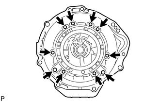
Remove the 10 bolts.
Remove the transmission housing.
35015G
7.REMOVE REAR ADAPTOR TRANSFER
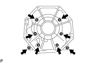
Remove the 8 bolts.
Remove the transmission case adapter.
- HINT:
-
Use a brass bar and a hammer to remove the transmission case adapter.
35015J
8.REMOVE TRANSMISSION CASE ADAPTER REAR OIL SEAL
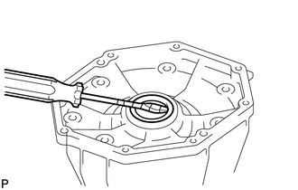
Using a screwdriver, pry out the oil seal.
- NOTICE:
-
Be careful not to damage the transmission case.
- HINT:
-
Wrap the tip of the screwdriver with tape.
35015E
9.REMOVE TRANSFER CASE ADAPTER RADIAL BALL BEARING
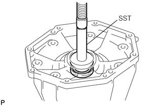
Using a screwdriver, remove the snap ring.
Using SST and a press, press out the bearing.
- SST
- 09950-60010 (09951-00650)
09950-70010 (09951-07150)
35104
10.FIX AUTOMATIC TRANSMISSION CASE SUB-ASSEMBLY
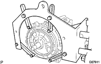
Install the transmission case to an overhaul attachment.
35106
11.REMOVE AUTOMATIC TRANSMISSION OIL PAN SUB-ASSEMBLY
- NOTICE:
-
Do not turn the transmission over as this will contaminate the valve body with foreign matter on the bottom of the pan.
Remove the drain plug and 20 bolts.
35106
12.INSPECT AUTOMATIC TRANSMISSION OIL PAN SUB-ASSEMBLY
35330
13.REMOVE VALVE BODY OIL STRAINER ASSEMBLY
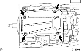
Turn over the transmission.
Remove the 4 bolts and oil strainer from the valve body.
Remove the O-ring from the oil strainer.
82125J
14.REMOVE TRANSMISSION WIRE
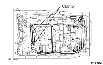
Remove the 2 bolts and 2 clamps, and disconnect the 2 ATF temperature sensors.
Disconnect the 7 connectors from the solenoid valves.
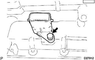
Remove the bolt from the case.
Pull the transmission wire out of the transmission case.
Remove the O-ring from the transmission wire.
35410
15.REMOVE TRANSMISSION VALVE BODY ASSEMBLY
Remove the bolt, detent spring cover and detent spring.
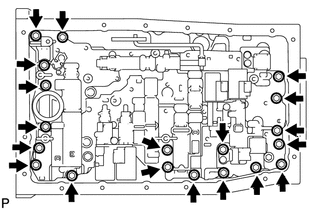
Remove the 19 bolts.
Remove the valve body.
35145C
16.REMOVE TRANSMISSION CASE GASKET
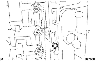
Remove the 3 gaskets.
35159
17.REMOVE BRAKE DRUM GASKET
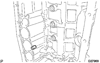
Remove the 3 gaskets.
35251
18.REMOVE CHECK BALL BODY
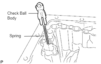
Remove the check ball body and spring.
35425A
19.REMOVE C-2 ACCUMULATOR PISTON
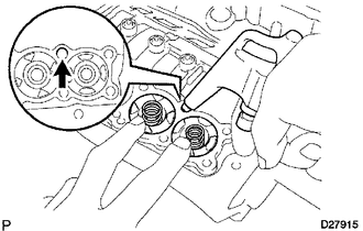
Apply compressed air to the oil hole to remove the C-2 accumulator piston and spring.
Remove the 2 O-rings from the piston.
- NOTICE:
-
Be careful as the C-3 and B-3 accumulator pistons may jump out.
35427K
20.REMOVE B-3 ACCUMULATOR PISTON
Apply compressed air to the oil hole to remove the B-3 accumulator piston and spring.
Remove the 2 O-rings from the piston.
- NOTICE:
-
Be careful as the C-3 accumulator piston may jump out.
35426D
21.REMOVE C-3 ACCUMULATOR PISTON
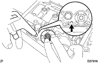
Apply compressed air to the oil hole to remove the C-3 accumulator piston and 2 springs.
Remove the 2 O-rings from the piston.
35424F
22.REMOVE C-1 ACCUMULATOR VALVE
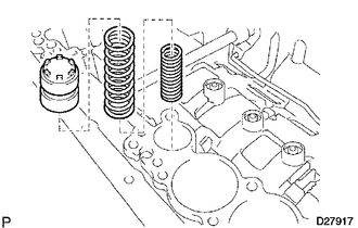
Remove the C-1 accumulator valve and 2 springs.
35595
23.REMOVE PARKING LOCK PAWL BRACKET
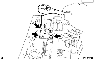
Remove the 3 bolts and bracket.
35501
24.REMOVE PARKING LOCK ROD SUB-ASSEMBLY
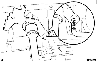
Disconnect the parking lock rod from the manual valve lever.
35556
25.REMOVE PARKING LOCK PAWL SHAFT
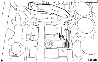
Pull out the parking lock pawl shaft from the front side, and then remove the lock pawl and spring.
Remove the E-ring from the shaft.
35505
26.REMOVE MANUAL VALVE LEVER SUB-ASSEMBLY
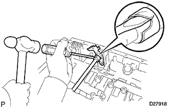
Using a hammer and screwdriver, cut off the spacer and remove it from the shaft.
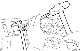
Using a pin punch and hammer, tap out the spring pin.
- HINT:
-
Slowly drive out the spring pin so that it does not fall into the transmission case.
Pull the manual valve lever shaft out through the case, and remove the manual valve lever.
35506F
27.REMOVE MANUAL VALVE LEVER SHAFT OIL SEAL
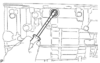
Using a screwdriver, pry out the 2 oil seals.
- NOTICE:
-
-
Be careful not to damage the transmission case.
- HINT:
-
Wrap the tip of the screwdriver with tape.
28.REMOVE OIL PUMP ASSEMBLY
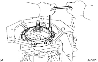
Remove the 10 bolts.
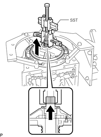
Using SST, remove the oil pump.
- SST
- 09950-40011 (09951-04010, 09952-04010, 09953-04020, 09954-04010, 09955-04031, 09958-04011)
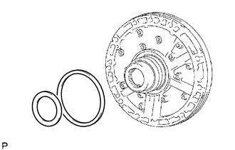
Remove the 2 thrust bearing races from the front oil pump.
29.REMOVE CLUTCH DRUM AND INPUT SHAFT ASSEMBLY
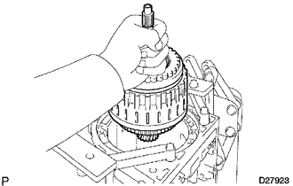
Remove the clutch drum and input shaft assembly from the transmission case.
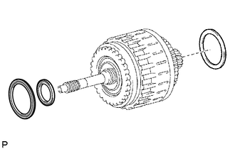
Remove the clutch drum thrust washer and 2 thrust needle roller bearings.
35780B
30.INSPECT NO. 2 1-WAY CLUTCH ASSEMBLY
35780B
31.REMOVE NO. 2 1-WAY CLUTCH ASSEMBLY
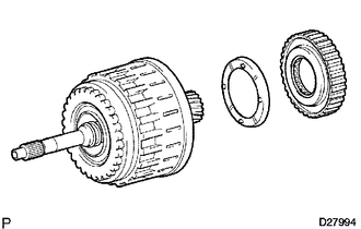
Remove the 1-way clutch and No. 2 clutch drum thrust washer from the clutch drum and input shaft assembly.
35601
32.FIX CLUTCH DRUM AND INPUT SHAFT ASSEMBLY
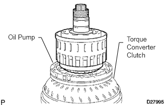
Place the oil pump onto the torque converter, and then place the clutch drum and input shaft assembly onto the oil pump.
35049
33.REMOVE REVERSE CLUTCH HUB SUB-ASSEMBLY
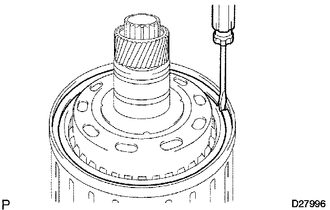
Using a screwdriver, remove the snap ring.
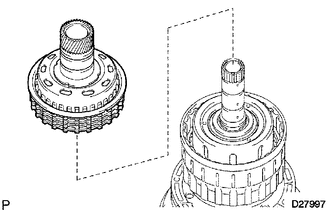
Remove the reverse clutch hub sub-assembly, reverse clutch reaction sleeve, clutch cushion, plate reverse clutch flange, 5 reverse clutch discs and 4 clutch plates from the clutch drum.
35659
34.REMOVE REVERSE CLUTCH REACTION SLEEVE
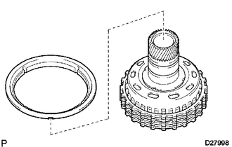
Remove the reverse clutch reaction sleeve from the reverse clutch hub.
35677C
35.REMOVE REAR CLUTCH DISC
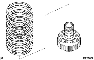
Remove the clutch cushion plate, reverse clutch flange, 5 discs and 4 plates from the reverse clutch hub.
35677C
36.INSPECT REAR CLUTCH DISC
35049
37.INSPECT REVERSE CLUTCH HUB SUB-ASSEMBLY
35061
38.REMOVE FORWARD CLUTCH HUB SUB-ASSEMBLY
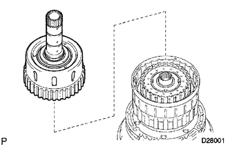
Remove the forward clutch hub from the clutch drum.
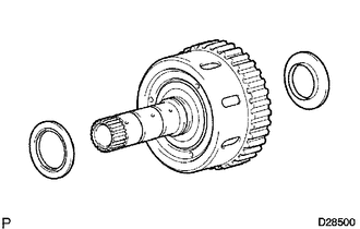
Remove the 2 thrust needle roller bearings from the forward clutch hub.
35061
39.INSPECT FORWARD CLUTCH HUB SUB-ASSEMBLY
35631
40.REMOVE MULTIPLE DISC CLUTCH HUB
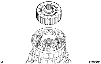
Remove the multiple disc clutch hub from the clutch drum.
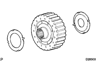
Remove the 2 thrust bearing races from the multiple disc clutch hub.
35701
41.REMOVE INPUT SHAFT ASSEMBLY
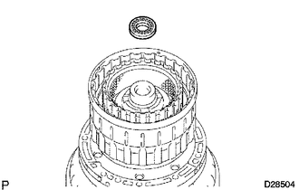
Remove the thrust needle roller bearing from the clutch drum.
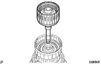
Remove the input shaft assembly from the clutch drum.
35712A
42.REMOVE INPUT SHAFT OIL SEAL RING
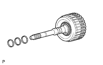
Remove the 3 oil seal rings from the input shaft.
35633B
43.REMOVE FORWARD MULTIPLE DISC CLUTCH DISC
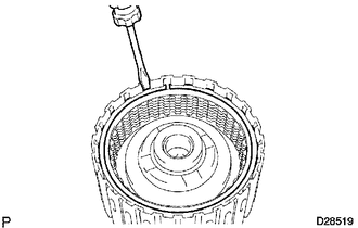
Using a screwdriver, remove the hole snap ring.
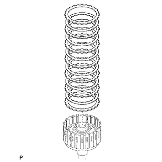
Remove the 2 flanges, 6 discs and 5 plates from the input shaft.
35633B
44.INSPECT FORWARD MULTIPLE DISC CLUTCH DISC
35668
45.REMOVE NO. 1 CLUTCH BALANCER
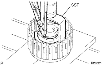
Place SST on the clutch balancer, and compress the return spring with a press.
- SST
- 09350-30020 (09350-07040, 09350-07070)
Using a snap ring expander, remove the snap ring.
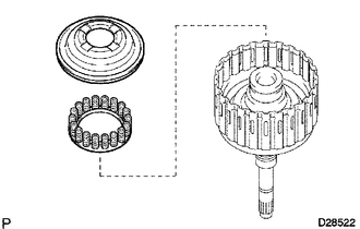
Remove the clutch balancer and forward clutch return spring from the input shaft assembly.
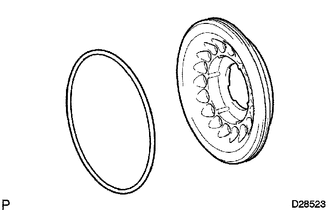
Remove the O-ring from the No. 1 clutch balancer.
35603A
46.INSPECT FORWARD CLUTCH RETURN SPRING SUB-ASSEMBLY
35612B
47.REMOVE FORWARD CLUTCH PISTON
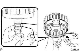
Hold the input shaft by hand and apply compressed air (392 kPa (4.0 kgf/cm2, 57 psi)) to the input shaft to remove the forward clutch piston.
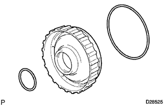
Remove the 2 O-rings from the forward clutch piston.
35649
48.REMOVE REVERSE CLUTCH FLANGE
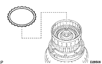
Remove the reverse clutch flange from the clutch drum.
35667A
49.REMOVE DIRECT CLUTCH DISC
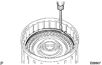
Using a screwdriver, remove the 2 hole snap rings from the clutch drum.
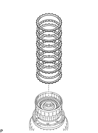
Remove the reverse clutch flange, 5 discs and 5 plates from the clutch drum.
35667A
50.INSPECT DIRECT CLUTCH DISC
35668
51.REMOVE NO. 3 CLUTCH BALANCER
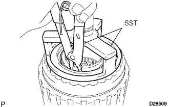
Place SST on the clutch balancer, and compress the return spring with a press.
- SST
- 09387-00070
Using SST, remove the snap ring.
- SST
- 09350-30020 (09350-07070)
35047
52.REMOVE REVERSE CLUTCH RETURN SPRING SUB-ASSEMBLY
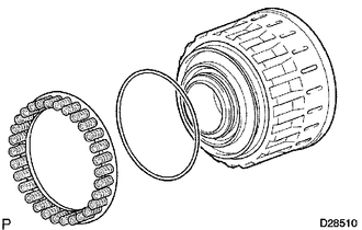
Remove the reverse clutch return spring and O-ring from the reverse clutch piston.
35048
53.INSPECT REVERSE CLUTCH RETURN SPRING SUB-ASSEMBLY
35048
54.REMOVE REVERSE CLUTCH PISTON SUB-ASSEMBLY
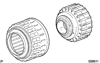
Remove the reverse clutch piston sub-assembly from the clutch drum.
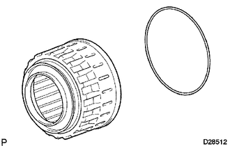
Remove the O-ring from the reverse clutch piston.
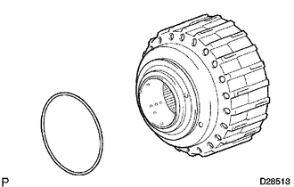
Remove the O-ring from the clutch drum.
35606A
55.REMOVE DIRECT CLUTCH PISTON SUB-ASSEMBLY
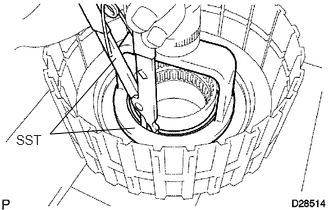
Place SST on the direct clutch piston, and compress the return spring with a press.
- SST
- 09320-89010
Using SST, remove the snap ring.
- SST
- 09350-30020 (09350-07070)
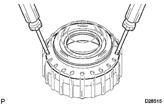
Using 2 screwdrivers, remove the direct clutch piston sub-assembly from the clutch drum.
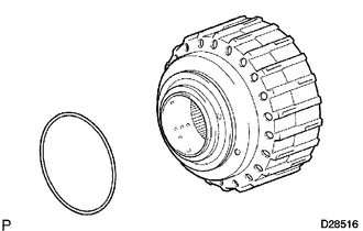
Remove the O-ring from the clutch drum.
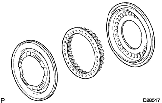
Remove the No. 2 clutch balancer and direct clutch return spring from the direct clutch piston.
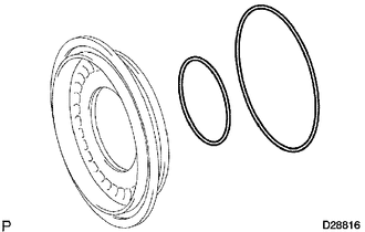
Remove the 2 O-rings from the direct clutch piston.
35604
56.INSPECT DIRECT CLUTCH RETURN SPRING SUB-ASSEMBLY
35679C
57.REMOVE NO. 3 BRAKE SNAP RING
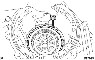
Using a screwdriver, remove the No. 3 brake snap ring from the case.
58.REMOVE NO. 3 BRAKE DISC
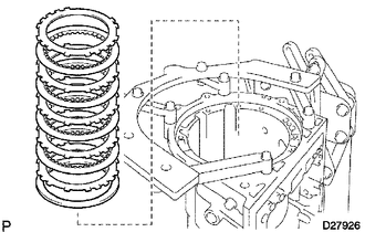
Remove the flange, 4 discs, 4 plates and cushion plate from the case.
59.INSPECT NO. 3 BRAKE DISC
35624J
60.REMOVE 2ND BRAKE PISTON HOLE SNAP RING
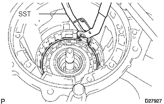
Using SST, remove the snap ring.
- SST
- 09350-30020 (09350-07060)
35790
61.REMOVE 1-WAY CLUTCH ASSEMBLY
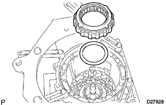
Remove the 1-way clutch assembly and No. 1 planetary carrier thrust washer from the case.
35664
62.REMOVE 2ND BRAKE CYLINDER
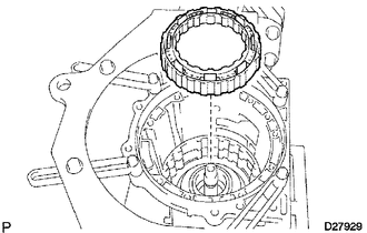
Remove the 2nd brake cylinder from the case.
35624
63.REMOVE 2ND BRAKE PISTON
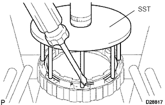
Using SST and a press, compress the return spring and remove the snap ring.
- SST
- 09351-40010
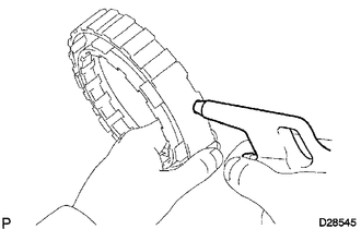
Hold the 2nd brake cylinder and apply compressed air (392 kPa (4.0 kgf/cm2, 57 psi)) to the 2nd brake cylinder to remove the 2nd brake piston.
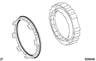
Remove the 2 O-rings from the 2nd brake piston.
35046
64.INSPECT NO. 3 BRAKE PISTON RETURN SPRING SUB-ASSEMBLY
35720
65.REMOVE FRONT PLANETARY GEAR ASSEMBLY
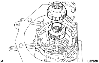
Remove the front planetary gear assembly and 1-way clutch inner race from the case.
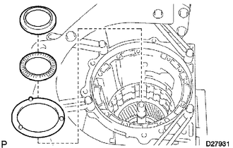
Remove the No. 5 thrust bearing race, thrust needle roller bearing and No. 2 planetary carrier thrust washer from the front planetary gear assembly.
35720
66.INSPECT FRONT PLANETARY GEAR ASSEMBLY
35790
67.INSPECT 1-WAY CLUTCH ASSEMBLY
68.REMOVE FRONT PLANETARY RING GEAR
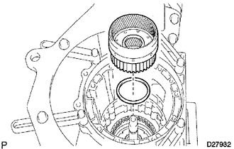
Remove the front planetary ring gear and thrust needle roller bearing from the transmission case.
35763
69.REMOVE CENTER PLANETARY RING GEAR
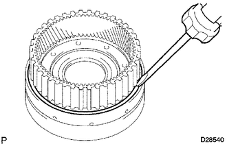
Using a screwdriver, remove the snap ring.
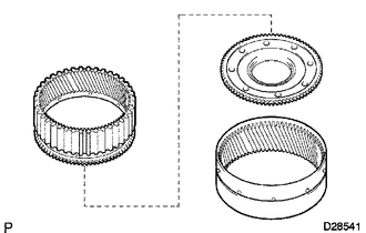
Remove the center planetary ring gear and front planetary ring gear flange from the front planetary ring gear.
35681A
70.REMOVE NO. 1 BRAKE DISC
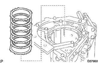
Remove the flange, 3 discs and 3 plates from the case.
35681A
71.INSPECT NO. 1 BRAKE DISC
35608K
72.REMOVE BRAKE PISTON RETURN SPRING SNAP RING
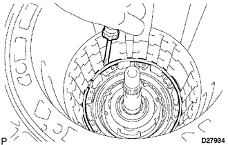
Using a screwdriver, remove the brake piston return spring snap ring from the case.
35608J
73.REMOVE BRAKE PISTON RETURN SPRING SUB-ASSEMBLY
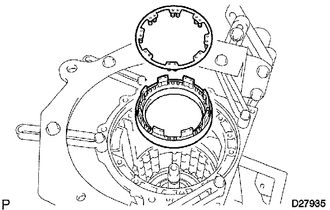
Remove the brake piston return spring and No. 1 brake piston with No. 1 brake cylinder from the transmission case.
35608J
74.INSPECT BRAKE PISTON RETURN SPRING SUB-ASSEMBLY
35621V
75.REMOVE NO. 1 BRAKE PISTON
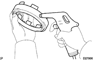
Hold the No. 1 brake cylinder and apply compressed air (392 kPa (4.0 kgf/cm2, 57 psi)) to No. 1 brake cylinder to remove the No. 1 brake piston.
- HINT:
-
If the piston does not pop out with compressed air, lift the piston out with needle-nose pliers.
Remove the 2 O-rings from the No. 1 brake piston.
35682A
76.REMOVE NO. 2 BRAKE DISC
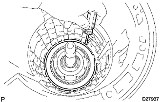
Using a screwdriver, remove the snap ring from the case.
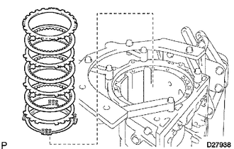
Remove the flange, 3 discs, 3 plates and brake piston return spring from the case.
35682A
77.INSPECT NO. 2 BRAKE DISC
35045
78.INSPECT NO. 2 BRAKE PISTON RETURN SPRING SUB-ASSEMBLY
35622G
79.REMOVE NO. 2 BRAKE PISTON
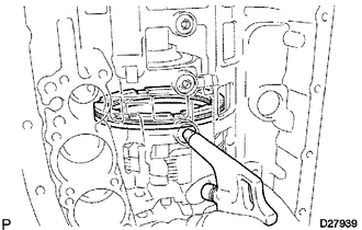
Apply compressed air (392 kPa (4.0 kgf/cm2, 57 psi)) to the transmission case to remove the No. 2 brake piston.
- HINT:
-
If the piston does not pop out with compressed air, lift the piston out with needle-nose pliers.
Remove the 2 O-rings from the No. 2 brake piston.
35750
80.REMOVE CENTER PLANETARY GEAR ASSEMBLY
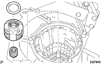
Remove the No. 6 thrust bearing race, center planetary gear and planetary sun gear from the case.
35750
81.INSPECT CENTER PLANETARY GEAR ASSEMBLY
35713
82.REMOVE INTERMEDIATE SHAFT
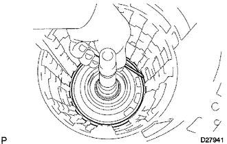
Using a screwdriver, remove the snap ring from the case.
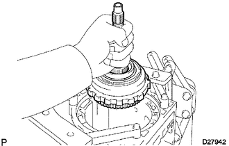
Remove the intermediate shaft with No. 3 1-way clutch assembly from the case.
35770C
83.INSPECT NO. 3 1-WAY CLUTCH ASSEMBLY
35770C
84.REMOVE NO. 3 1-WAY CLUTCH ASSEMBLY
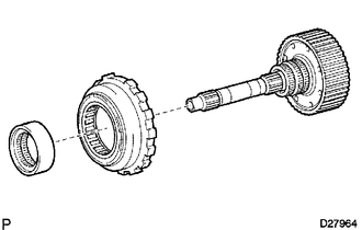
Remove the No. 3 1-way clutch assembly and 1-way clutch inner race from the intermediate shaft.
35077D
85.REMOVE REAR PLANETARY RING GEAR FLANGE SUB-ASSEMBLY
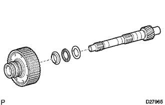
Remove the planetary ring gear flange, No. 7 thrust bearing race, thrust needle roller bearing and No. 8 thrust bearing race from the intermediate shaft.
35077D
86.INSPECT REAR PLANETARY RING GEAR FLANGE SUB-ASSEMBLY
35713
87.INSPECT INTERMEDIATE SHAFT
35639B
88.REMOVE BRAKE PLATE STOPPER SPRING
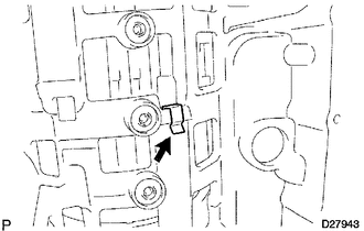
89.REMOVE NO. 4 BRAKE DISC
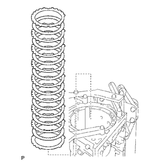
Remove the 7 plates, 8 discs and 2 flanges from the case.
35684
90.INSPECT NO. 4 BRAKE DISC
35719B
91.REMOVE REAR PLANETARY GEAR ASSEMBLY
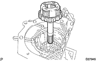
Remove the rear planetary gear assembly from the case.
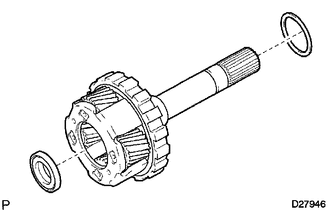
Remove the 2 thrust needle roller bearings from the rear planetary gear.
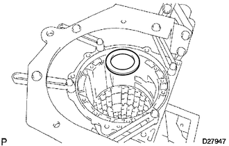
Remove the No. 9 thrust bearing from the case.
35719B
92.INSPECT REAR PLANETARY GEAR ASSEMBLY
35068
93.REMOVE 1ST AND REVERSE BRAKE RETURN SPRING SUB-ASSEMBLY
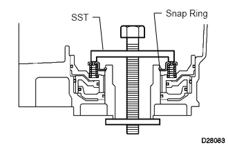
Place SST on the spring retainer and compress the brake return spring.
- SST
- 09350-30020 (09350-07050)
Using SST, remove the snap ring and brake return spring.
- SST
- 09350-30020 (09350-07070)
35068
94.INSPECT 1ST AND REVERSE BRAKE RETURN SPRING SUB-ASSEMBLY
35623H
95.REMOVE 1ST AND REVERSE BRAKE PISTON
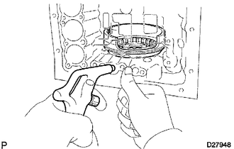
Apply compressed air (392 kPa (4.0 kgf/cm2, 57 psi)) to the transmission case to remove the 1st and reverse brake piston.
- HINT:
-
If the piston does not pop out with compressed air, lift the piston out with needle-nose pliers.
Remove the O-ring from the 1st and reverse brake piston.
35626
96.REMOVE BRAKE REACTION SLEEVE
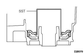
Using SST, remove the reaction sleeve.
- SST
- 09350-30020 (09350-07080)
Remove the O-ring from the reaction sleeve.
35629A
97.REMOVE NO. 4 BRAKE PISTON
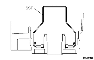
Using SST, remove the brake piston.
- SST
- 09350-30020 (09350-07090)
Remove the 2 O-rings from the brake piston.