Home › Drivetrain › A750F (AUTOMATIC TRANSMISSION / TRANSAXLE) › AUTOMATIC TRANSMISSION SYSTEM(for 1GR-FE) › 2015.08–2017.08
RM2660E _52 Drivetrain _052806 A750F AUTOMATIC TRANSMISSION / TRANSAXLE _0255290 AUTOMATIC TRANSMISSION SYSTEM(for 1GR-FE) J

A750F AUTOMATIC TRANSMISSION / TRANSAXLE  AUTOMATIC TRANSMISSION SYSTEM(for 1GR-FE)  Transmission Control Switch Circuit  


DESCRIPTION

When moving the shift lever to S using the transmission control switch, it is possible to switch the shift range between "1" (1st range) and "5" (5th range).

Shifting to "+" once raises the shift range by one, and shifting to "-" lowers the shift range by one.

WIRING DIAGRAM
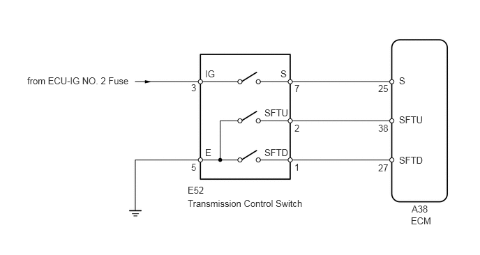
C176192E31
5.646,1.24 5.875,1.406 0.229,0.167 10 false 25 3.948,2.198 4.417,2.396 0.469,0.198 10 false SFTD 3.948,1.604 4.417,1.802 0.469,0.198 10 false SFTU 4.188,1.021 4.313,1.219 0.125,0.198 10 false S 3.063,1.021 3.302,1.219 0.24,0.198 10 false IG 3.063,2.198 3.302,2.396 0.24,0.198 10 false E 5.958,1.125 6.385,1.323 0.427,0.198 10 false S 5.646,1.833 5.875,2 0.229,0.167 10 false 38 5.958,1.708 6.385,1.906 0.427,0.198 10 false SFTU 5.646,2.427 5.875,2.594 0.229,0.167 10 false 27 5.958,2.313 6.385,2.51 0.427,0.198 10 false SFTD 2.802,2.76 3.229,2.958 0.427,0.198 10 false E52 2.802,2.958 4.583,3.156 1.781,0.198 10 false Transmission Control Switch 0.406,1.125 2.104,1.323 1.698,0.198 10 false from ECU-IG NO. 2 Fuse 6.146,3.042 6.448,3.208 0.302,0.167 10 false A38 6.135,3.219 6.563,3.417 0.427,0.198 10 false ECM 2.854,1.229 3.021,1.396 0.167,0.167 10 false 3 2.854,2.417 3.042,2.583 0.188,0.167 10 false 5 4.396,1.24 4.76,1.406 0.365,0.167 10 false 7 4.396,1.833 4.677,2 0.281,0.167 10 false 2 4.396,2.417 4.719,2.583 0.323,0.167 10 false 1

PROCEDURE

1.INSPECT TRANSMISSION CONTROL SWITCH
a.
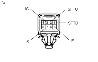
C203344E39
1.604,0.76 1.073,0.323 false 1.083,1.406 1.615,0.979 false 1.792,0.74 2.292,0.354 false 1.958,0.781 2.313,0.781 false 1.948,0.969 2.417,1.406 false 0.052,0 0.365,0.198 0.313,0.198 10 false *a 0.875,0.229 1.115,0.427 0.24,0.198 10 false IG 0.927,1.385 1.115,1.583 0.188,0.198 10 false S 2.375,0.24 2.781,0.438 0.406,0.198 10 false SFTU 2.385,0.729 2.75,0.917 0.365,0.188 10 false SFTD 2.5,1.354 2.74,1.552 0.24,0.198 10 false E

Disconnect the transmission control switch connector.


b.

Measure the resistance according to the value(s) in the table below.

Standard Resistance:
Tester Connection Condition Specified Condition
3 (IG) - 7 (S) Shift lever in S, "+" or "-" Below 1 Ω
2 (SFTU) - 5 (E) Shift lever held in "+"
(Up-shift)
Below 1 Ω
1 (SFTD) - 5 (E) Shift lever held in "-"
(Down-shift)
Below 1 Ω
3 (IG) - 7 (S) Shift lever not in S, "+" or "-" 10 kΩ or higher
2 (SFTU) - 5 (E) Shift lever in S 10 kΩ or higher
1 (SFTD) - 5 (E) Shift lever in S 10 kΩ or higher


Text in Illustration
*a Front view of wire harness connector
(Transmission Control Switch)


OK

2.CHECK HARNESS AND CONNECTOR (TRANSMISSION CONTROL SWITCH - BATTERY, BODY GROUND)

NG

REPLACE TRANSMISSION CONTROL SWITCH (TRANSMISSION FLOOR SHIFT ASSEMBLY)

2.CHECK HARNESS AND CONNECTOR (TRANSMISSION CONTROL SWITCH - BATTERY, BODY GROUND)
a.
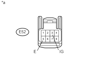
U164958E02
1.802,1.188 2.01,1.708 false 1.281,1.729 1.469,1.385 false 0.052,0 0.365,0.198 0.313,0.198 10 false *a 2.042,1.677 2.354,1.875 0.313,0.198 10 false IG 1.156,1.677 1.469,1.875 0.313,0.198 10 false E 0.646,1 1.021,1.229 0.375,0.229 10 false E52

Disconnect the transmission control switch connector.


b.

Turn the engine switch on (IG).


c.

Measure the voltage according to the value(s) in the table below.

Standard Voltage:
Tester Connection Condition Specified Condition
E52-3 (IG) - Body ground Engine switch on (IG) 11 to 14 V
E52-3 (IG) - Body ground Engine switch off Below 1 V


d.

Turn the engine switch off.


e.

Measure the resistance according to the value(s) in the table below.

Standard Resistance:
Tester Connection Condition Specified Condition
E52-5 (E) - Body ground Always Below 1 Ω


Text in Illustration
*a Front view of wire harness connector
(to Transmission Control Switch)


OK

3.CHECK HARNESS AND CONNECTOR (TRANSMISSION CONTROL SWITCH - ECM)

NG

REPAIR OR REPLACE HARNESS OR CONNECTOR

3.CHECK HARNESS AND CONNECTOR (TRANSMISSION CONTROL SWITCH - ECM)
a.
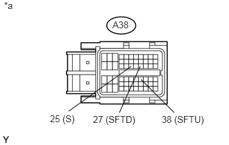
U164948E02
1.031,1.677 1.969,1 false 1.792,1.698 2.104,1 false 2.615,1.698 2.115,1.198 false 0.063,0 0.375,0.198 0.313,0.198 10 false *a 0.75,1.708 1.198,1.906 0.448,0.198 10 false 25 (S) 1.396,1.719 2.115,1.917 0.719,0.198 10 false 27 (SFTD) 2.427,1.719 3.146,1.917 0.719,0.198 10 false 38 (SFTU) 1.688,0.292 2.063,0.521 0.375,0.229 10 false A38

Disconnect the ECM connector.


b.

Turn the engine switch on (IG).


c.

Measure the voltage according to the value(s) in the table below.

Standard Voltage:
Tester Connection Condition Specified Condition
A38-25 (S) - Body ground
·

Engine switch on (IG)

·

Shift lever in S, "+" or "-"


11 to 14 V
A38-25 (S) - Body ground
·

Engine switch on (IG)

·

Shift lever not in S, "+" or "-"


Below 1 V


d.

Turn the engine switch off.


e.

Measure the resistance according to the value(s) in the table below.

Standard Resistance:
Tester Connection Condition Specified Condition
A38-38 (SFTU) - Body ground Shift lever held in "+"
(Up-shift)
Below 1 Ω
A38-27 (SFTD) - Body ground Shift lever held in "-"
(Down-shift)
Below 1 Ω
A38-38 (SFTU) - Body ground Shift lever in S 10 kΩ or higher
A38-27 (SFTD) - Body ground Shift lever in S 10 kΩ or higher


Text in Illustration
*a Front view of wire harness connector
(to ECM)


OK

NG

REPAIR OR REPLACE HARNESS OR CONNECTOR