DRIVE SHAFT / PROPELLER SHAFT PROPELLER SHAFT ASSEMBLY INSPECTION
PROCEDURE

 37110
1.INSPECT REAR PROPELLER SHAFT ASSEMBLY
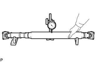
Using a dial indicator, measure the propeller shaft runout.
- Maximum runout:
0.8 mm (0.031 in.)
If the shaft runout is more than the maximum, replace the shaft.
2.INSPECT SPIDER BEARING
- NOTICE:
-
Be careful not to grip the propeller shaft tube too tightly in a vise as this will cause deformation.
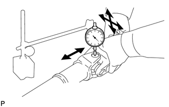
Check the spider bearings for wear or damage.
Check the axial play of each spider bearing by turning the yoke while holding the shaft tightly.
- Maximum bearing axial play:
0 mm (0 in.)
If the axial play is more than the maximum, replace the spider bearing.
3.FILL PROPELLER SHAFT WITH GREASE
Fill each of the grease fitting holes of the propeller shaft with MP grease.
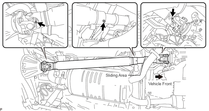
- NOTICE:
-
Stop filling the grease fitting hole on the middle portion of the propeller shaft once the sliding portion starts extending.
Drive the vehicle.
- NOTICE:
-
Check the safety of the surrounding areas.
- HINT:
-
Move the vehicle forward and in reverse 5 times and strongly apply the brake.
Lift up the vehicle and wipe off any excess grease as a result of driving.