Home › Suspension › SUSPENSION CONTROL › ACTIVE HEIGHT CONTROL SUSPENSION › from 2015.08
RM2660E _53 Suspension _052813 SUSPENSION CONTROL _0255367 ACTIVE HEIGHT CONTROL SUSPENSION J

SUSPENSION CONTROL  ACTIVE HEIGHT CONTROL SUSPENSION  ECU Power Source Circuit  


DESCRIPTION

This circuit supplies the power source to the suspension control ECU.

WIRING DIAGRAM
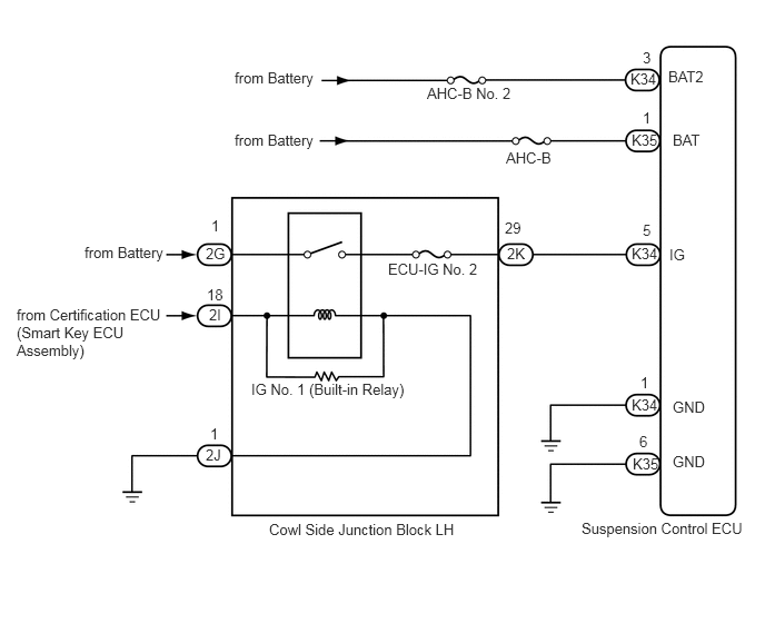
C347683E05
5.448,4.865 7.063,5.094 1.615,0.229 10 false Suspension Control ECU 6.302,3.729 6.76,3.938 0.458,0.208 10 false GND 6.302,4.24 6.76,4.448 0.458,0.208 10 false GND 5.917,3.708 6.188,3.854 0.271,0.146 10 false K34 5.927,4.26 6.219,4.406 0.292,0.146 10 false K35 6.271,2.302 6.458,2.49 0.188,0.188 10 false IG 5.917,2.292 6.188,2.448 0.271,0.156 10 false K34 6.021,2.073 6.125,2.24 0.104,0.167 10 false 5 6,3.5 6.104,3.646 0.104,0.146 10 false 1 5.99,4.052 6.104,4.219 0.115,0.167 10 false 6 4.75,2.292 4.958,2.469 0.208,0.177 10 false 2K 4.729,2.052 4.99,2.24 0.26,0.188 10 false 29 3.635,2.438 4.563,2.646 0.927,0.208 10 false ECU-IG No. 2 2.354,3.563 3.948,3.76 1.594,0.198 10 false IG No. 1 (Built-in Relay) 1.927,2.292 2.198,2.469 0.271,0.177 10 false 2G 1.979,2.031 2.073,2.167 0.094,0.135 10 false 1 1.958,2.865 2.177,3.021 0.219,0.156 10 false 2I 1.938,2.677 2.146,2.823 0.208,0.146 10 false 18 1.927,4.177 2.135,4.323 0.208,0.146 10 false 2J 1.969,3.979 2.083,4.125 0.115,0.146 10 false 1 0.156,2.865 1.646,3.51 1.49,0.646 10 false from Certification ECU (Smart Key ECU Assembly) 0.792,2.281 1.604,2.49 0.813,0.208 10 false from Battery 2.521,4.875 4.427,5.115 1.906,0.24 10 false Cowl Side Junction Block LH 6.26,0.635 6.667,0.823 0.406,0.188 10 false BAT2 6.302,1.229 6.708,1.417 0.406,0.188 10 false BAT 4,0.792 4.927,1 0.927,0.208 10 false AHC-B No. 2 4.74,1.396 5.344,1.604 0.604,0.208 10 false AHC-B 5.906,0.656 6.177,0.813 0.271,0.156 10 false K34 5.917,1.229 6.188,1.385 0.271,0.156 10 false K35 6.021,0.458 6.125,0.625 0.104,0.167 10 false 3 6.021,1.021 6.115,1.156 0.094,0.135 10 false 1 2.198,0.646 3.01,0.854 0.813,0.208 10 false from Battery 2.198,1.229 3.01,1.438 0.813,0.208 10 false from Battery

CAUTION / NOTICE / HINT

NOTICE:
·

Before performing troubleshooting, inspect the connectors of related circuits.

·

If the suspension control ECU or height control sensor is replaced, the vehicle height offset calibration must be performed (See page Suspension>SUSPENSION CONTROL>ACTIVE HEIGHT CONTROL SUSPENSION>INITIALIZATION).


PROCEDURE

1.READ VALUE USING GTS (IG POWER SOURCE VOLTAGE)
a.

Turn the engine switch off.


b.

Connect the GTS to the DLC3.


c.

Turn the engine switch on (IG) and the GTS on.


d.

Read the "IG Power Source Voltage" item in the Data List..

AHC
Tester Display Measurement Item/Range Normal Condition Diagnostic Note
IG Power Source Voltage Power supply voltage /
min.: 0 V
max.: 255 V
Engine switch on (IG): 11 to 14 V -

OK:

11 to 14 V


OK

NG

2.INSPECT FUSE (ECU-IG NO. 2)
a.

Remove the ECU-IG No. 2 fuse from the cowl side junction block LH.


b.

Measure the resistance according to the value(s) in the table below.

Standard Resistance:
Tester Connection Condition Specified Condition
ECU-IG No. 2 fuse Always Below 1 Ω


OK

3.INSPECT COWL SIDE JUNCTION BLOCK LH (IG NO. 1 RELAY)

NG

7.CHECK HARNESS AND CONNECTOR (COWL SIDE JUNCTION BLOCK LH - SUSPENSION CONTROL ECU)
3.INSPECT COWL SIDE JUNCTION BLOCK LH (IG NO. 1 RELAY)
a.

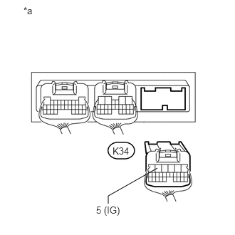
Disconnect the K34 suspension control ECU connector.

b.
U164813E02
2.302,2.458 1.583,2.865 1.583,2.865 1.583,2.979 false 0.344,0.073 0.552,0.292 0.208,0.219 10 false *a 1.406,2.99 1.833,3.188 0.427,0.198 10 false 5 (IG) 1.646,2.125 1.906,2.271 0.26,0.146 10 false K34

Measure the voltage according to the value(s) in the table below.

Standard Voltage:
Tester Connection Condition Specified Condition
K34-5 (IG) - Body ground Engine switch on (IG) 11 to 14 V


Text in Illustration
*a Rear view of wire harness connector
(to Suspension Control ECU)


OK

REPLACE SUSPENSION CONTROL ECU

NG

4.CHECK HARNESS AND CONNECTOR (COWL SIDE JUNCTION BLOCK LH - SUSPENSION CONTROL ECU AND BODY GROUND
a.

Disconnect the K34 and K35 suspension control ECU connectors.


b.

Disconnect the 2K cowl side junction block LH connector.

c.

Measure the resistance according to the value(s) in the table below.

Standard Resistance:
Tester Connection Condition Specified Condition
K34-5 (IG) - 2K-29 Always Below 1 Ω
K34-1 (GND) - Body ground Always Below 1 Ω
K35-6 (GND) - Body ground Always Below 1 Ω


OK

5.CHECK HARNESS AND CONNECTOR (BATTERY - COWL SIDE JUNCTION BLOCK LH)

NG

REPAIR OR REPLACE HARNESS OR CONNECTOR

5.CHECK HARNESS AND CONNECTOR (BATTERY - COWL SIDE JUNCTION BLOCK LH)
a.

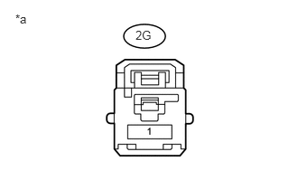
Disconnect the 2G cowl side junction block LH connector.


b.
U166429E02
1.563,0.323 1.948,0.51 0.385,0.188 10 false 2G 0.177,0.135 0.563,0.323 0.385,0.188 10 false *a

Measure the voltage according to the value(s) in the table below.

Standard Voltage:
Tester Connection Condition Specified Condition
2G-1 - Body ground Always 11 to 14 V


Text in Illustration
*a Front view of wire harness connector
(to Cowl Side Junction Block LH)


OK

6.CHECK HARNESS AND CONNECTOR (MAIN BODY ECU - COWL SIDE JUNCTION BLOCK LH AND BODY GROUND)

NG

REPAIR OR REPLACE HARNESS OR CONNECTOR

6.CHECK HARNESS AND CONNECTOR (MAIN BODY ECU - COWL SIDE JUNCTION BLOCK LH AND BODY GROUND)
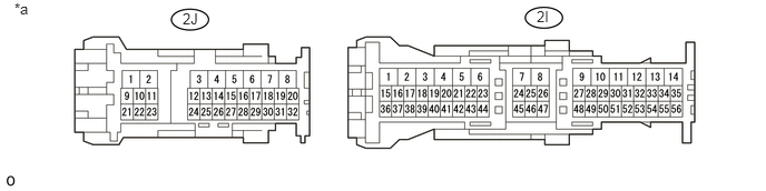
U165760E02
1.708,0.094 1.979,0.302 0.271,0.208 10 false 2J 0.135,0 0.51,0.24 0.375,0.24 10 false *a 5.021,0.073 5.292,0.281 0.271,0.208 10 false 2I

Text in Illustration
*a Front view of wire harness connector
(to Cowl Side Junction Block LH)
- -

a.

Disconnect the 2I and 2J cowl side junction block LH connectors.


b.

Measure the voltage and resistance according to the value(s) in the tables below.

Standard Voltage:
Tester Connection Condition Specified Condition
2I-18 - Body ground Engine switch on (IG) 11 to 14 V


Standard Resistance:
Tester Connection Condition Specified Condition
2J-1 - Body ground Always Below 1 Ω


OK

7.CHECK HARNESS AND CONNECTOR (COWL SIDE JUNCTION BLOCK LH - SUSPENSION CONTROL ECU)

NG

REPAIR OR REPLACE HARNESS OR CONNECTOR

7.CHECK HARNESS AND CONNECTOR (COWL SIDE JUNCTION BLOCK LH - SUSPENSION CONTROL ECU)
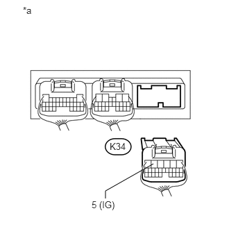
a.

Disconnect the K34 suspension control ECU connector.

b.
U164814E02
2.302,2.458 1.583,2.865 1.583,2.865 1.583,2.979 false 0.344,0.073 2.656,0.479 2.313,0.406 10 false *a 1.375,2.99 1.802,3.188 0.427,0.198 10 false 5 (IG) 1.646,2.115 1.906,2.26 0.26,0.146 10 false K34

Measure the resistance according to the value(s) in the table below.

Standard Resistance:
Tester Connection Condition Specified Condition
K34-5 (IG) - Body ground Always 10 kΩ or higher

Text in Illustration
*a Rear view of wire harness connector
(to Suspension Control ECU)


HINT:

If a fuse is blown, replace the fuse.


OK

REPLACE COWL SIDE JUNCTION BLOCK LH

NG

REPAIR OR REPLACE HARNESS OR CONNECTOR