SUSPENSION CONTROL STABILIZER CONTROL VALVE(w/ KDSS) REASSEMBLY
PROCEDURE

 48867
1.INSTALL STABILIZER CONTROL ADAPTER SHUTTER VALVE (for Lower Chamber Side)
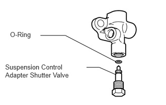
Apply a small amount of suspension fluid to a new O-ring and install it to the shutter valve.
Install the shutter valve to the adapter housing.
- Torque:
- 14 N*m (140 kgf*cm, 10 ft.*lbf)
48867
2.INSTALL STABILIZER CONTROL ADAPTER SHUTTER VALVE 2 Type (for Upper Chamber Side)
- HINT:
-
Use the same procedures described for the lower chamber side.
15703
3.INSTALL OIL NOZZLE VALVE SUB-ASSEMBLY (for Lower Chamber Side)
Before installing the oil nozzle valve, apply suspension fluid to the oil nozzle valve O-ring.
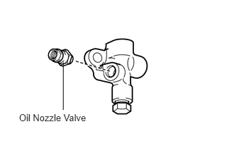
Install the oil nozzle valve to the adapter housing.
- Torque:
- 12 N*m (122 kgf*cm, 9 ft.*lbf)
15703
4.INSTALL OIL NOZZLE VALVE SUB-ASSEMBLY 2 Type (for Upper Chamber Side)
- HINT:
-
Use the same procedures described for the lower chamber side.
88375G
5.INSTALL SERVICE VALVE CAP (for Lower Chamber Side)
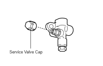
Install the valve cap to the oil nozzle valve.
- Torque:
- 0.6 N*m (6.0 kgf*cm, 5.0 in.*lbf)
88375G
6.INSTALL SERVICE VALVE CAP 2 Type (for Upper Chamber Side)
- HINT:
-
Use the same procedures described for the lower chamber side.