TIRE PRESSURE MONITORING TIRE PRESSURE WARNING SYSTEM TC and CG Terminal Circuit
DESCRIPTION
DTC output mode is set by connecting terminals 13 (TC) and 4 (CG) of the DLC3. The DTCs are indicated by the tire pressure warning light blinking pattern.
WIRING DIAGRAM
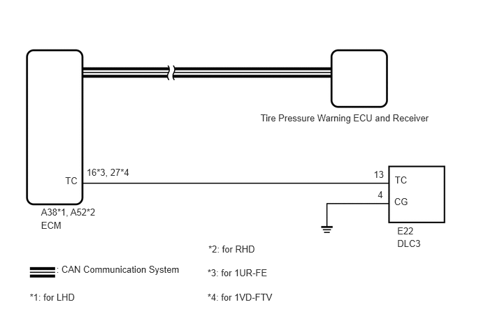
- HINT:
-
If the tire pressure warning light blinks continuously, a ground short in the wiring of terminal TC of the DLC3 or an internal ground short in each ECU is suspected.
PROCEDURE
Turn the engine switch off.
Connect the GTS to the DLC3.
Turn the engine switch on (IG) and turn the GTS on.
Enter the following menus: "CAN Bus Check" from the "System Select" screen.
Check the CAN communication system (for LHD: See page Power Source / Network>NETWORKING>CAN COMMUNICATION SYSTEM(for LHD)>DIAGNOSIS SYSTEM, for RHD: See page Power Source / Network>NETWORKING>CAN COMMUNICATION SYSTEM(for RHD)>DIAGNOSIS SYSTEM).
- OK:
The CAN communication system is normal.
- Result:
Result Proceed to OK A NG (for LHD) B NG (for RHD) C
A
B
C
Disconnect the ECM A38*1, A52*2 connector.
*1: for LHD
*2: for RHD
Measure the resistance according to the value(s) in the table below.
- Standard Resistance:
for LHD Tester Connection Condition Specified Condition E22-13 (TC) - A38-16*1, 27*2(TC) Always Below 1 Ω E22-13 (TC) or A38-16*1, 27*2(TC) - Body ground Always 10 kΩ or higher E22-4 (CG) - Body ground Always Below 1 Ω
*1: for 1UR-FE
*2: for 1VD-FTV
- Standard Resistance:
for RHD Tester Connection Condition Specified Condition E22-13 (TC) - A52-27 (TC) Always Below 1 Ω E22-13 (TC) or A52-27 (TC) - Body ground Always 10 kΩ or higher E22-4 (CG) - Body ground Always Below 1 Ω
OK
NG
Connect the ECM A38*1, A52*2 connector.
*1: for LHD
*2: for RHD
Measure the voltage according to the value(s) in the table below.
- Standard Voltage:
Tester Connection Switch Condition Specified Condition E22-13 (TC) - E22-4 (CG) Engine switch on (IG) 11 to 14 V
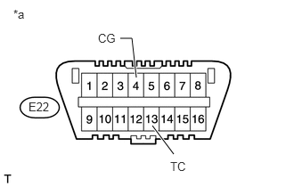
| *a | Front view of DLC3 |
- Result:
Result Proceed to OK A NG (for 1UR-FE) B NG (for 1VD-FTV) C
A
B
C