POWER ASSIST SYSTEMS VANE PUMP(for 3UR-FE) INSPECTION
PROCEDURE

 1.INSPECT VANE PUMP SHAFT AND BUSH IN VANE PUMP FRONT HOUSING
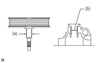
Using a micrometer, measure the outer diameter [a] of the vane pump shaft.
Using a vernier caliper, measure the inner diameter [b] of the vane pump front housing bush.
Calculate the oil clearance.
Oil clearance = Inner diameter of the bush [b] - Outer diameter of the shaft [a]
- Maximum oil clearance:
0.07 mm (0.00276 in.)
If the oil clearance is more than the maximum, replace the vane pump assembly.
2.INSPECT VANE PUMP ROTOR AND VANE PUMP PLATE
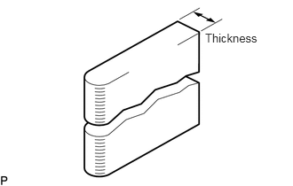
Using a micrometer, measure the thickness of the vane pump plates.
- Standard thickness:
1.405 to 1.411 mm (0.0553 to 0.0556 in.)
If the thickness is not as specified, replace the vane pump assembly.
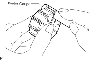
Using a feeler gauge, measure the clearance between the side face of the vane pump rotor groove and the vane pump plate.
- Maximum clearance:
0.03 mm (0.00118 in.)
If the clearance is more than the maximum, replace the vane pump assembly.
3.INSPECT FLOW CONTROL VALVE ASSEMBLY
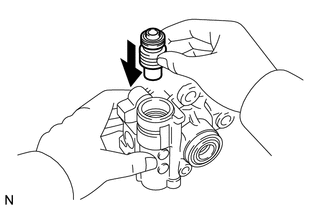
Coat the flow control valve with power steering fluid and check that it falls smoothly into the valve hole by its own weight.
If the control valve does not fall into the hole smoothly, replace the vane pump assembly.
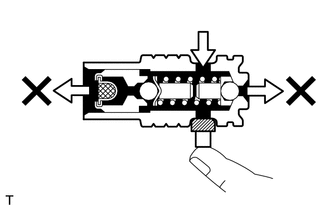
Check the flow control valve for leakage. Close one of the holes and apply 392 to 490 kPa (4.0 to 5.0 kgf/cm2, 57 to 71 psi) of compressed air into the opposite side hole, and confirm that air does not come out from the end hole.
If air leaks, replace the vane pump assembly.
4.INSPECT FLOW CONTROL VALVE COMPRESSION SPRING
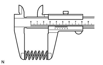
Using a vernier caliper, measure the free length of the compression spring.
- Minimum free length:
31.3 mm (1.23 in.)
If the length is less than the minimum, replace the vane pump assembly.
5.INSPECT PRESSURE PORT UNION
Visually check the pressure port union for fluid leaks.
If there is a leak, replace the vane pump assembly.
6.INSPECT TOTAL PRELOAD
Check that the pump rotates smoothly without abnormal noise.
Temporarily install a service bolt.
- Recommended service bolt:
- Thread diameter:
10 mm (0.394 in.)
- Thread pitch:
1.25 mm (0.0492 in.)
- Bolt length:
50 mm (1.97 in.)
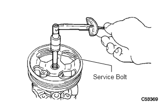
Using a torque wrench, measure the pump rotating torque.
- Standard rotating torque:
0.3 N*m (3 kgf*cm, 2 in.*lbf) or less
If the rotating torque is not as specified, check the vane pump housing oil seal.