Home › Steering › STEERING COLUMN › STEERING WHEEL › 2014.08–2015.08
RM2660E _55 Steering _052826 STEERING COLUMN _0255456 STEERING WHEEL G

STEERING COLUMN  STEERING WHEEL  INSPECTION  


CAUTION / NOTICE / HINT

CAUTION:

The vehicle is equipped with an SRS (Supplemental Restraint System) which includes components such as airbags. Before servicing (including removal or installation of parts), be sure to read the PRECAUTION in the SRS (See page General>INTRODUCTION>REPAIR INSTRUCTION>PRECAUTION).


PROCEDURE

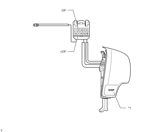
Hide 84250A 1.INSPECT STEERING PAD SWITCH ASSEMBLY (w/ DISP Switch)

a.

Disconnect the z36 switch connector.

E158678E03
3.458,1.531 3.26,2.281 3.26,2.281 2.99,2.281 true 3.01,0.448 3.229,0.448 3.229,0.448 3.458,1.271 true 5.031,4.073 5.323,4.771 5.323,4.771 5.573,4.771 true 2.656,2.198 2.969,2.385 0.313,0.188 10 false +DP 2.688,0.375 2.99,0.583 0.302,0.208 10 false -DP 5.667,4.688 6.042,4.896 0.375,0.208 10 false *1

Text in Illustration
*1 DISP Switch - -

Measure the resistance according to the value(s) in the table below.

Standard Resistance:
Tester Connection Switch Condition Specified Condition
2 (-DP) - 7 (+DP) DISP switch pushed Below 2.5 Ω


If the result is not as specified, replace the steering switch assembly.


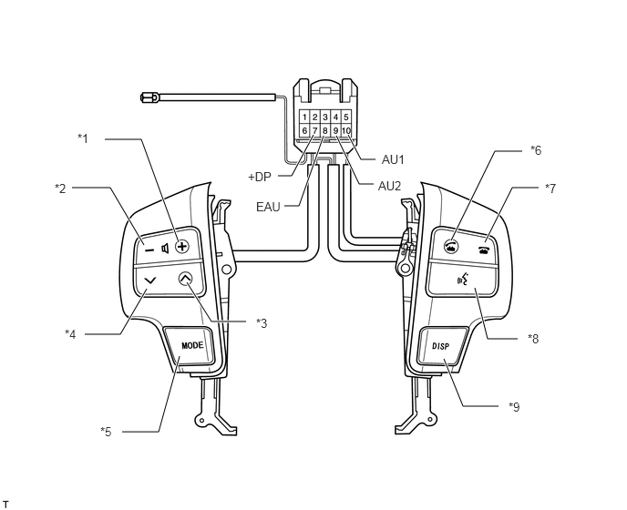
Hide 84250A 2.INSPECT STEERING PAD SWITCH ASSEMBLY (w/ AUDIO + TEL + VOICE + DISP Switch)

a.

Disconnect the z36 switch connector.

E155690E14
3.177,2.01 3.333,2.01 3.333,2.01 3.583,1.542 true 3.25,2.354 3.417,2.354 3.417,2.354 3.698,1.552 true 4.271,2.104 4.104,2.104 4.104,2.104 3.844,1.552 true 3.979,1.542 4.125,1.823 4.125,1.823 4.292,1.823 true 5.156,2.75 5.656,1.729 5.656,1.729 5.969,1.729 true 5.542,2.771 5.854,2.146 5.854,2.146 6.156,2.146 true 5.427,3.292 5.573,3.875 5.573,3.875 5.917,3.875 true 5.073,4.104 5.292,4.646 5.292,4.646 5.698,4.646 true 2.042,2.771 1.615,1.594 1.615,1.594 1.198,1.594 true 1.646,2.802 1.26,2.146 1.26,2.146 0.823,2.146 true 2.135,3.229 2.417,3.677 2.417,3.677 2.813,3.677 true 1.677,3.302 1.375,3.823 1.375,3.823 0.969,3.823 true 2.052,4.073 1.813,4.938 1.813,4.938 1.396,4.938 true 2.833,1.938 3.271,2.177 0.438,0.24 10 false +DP 2.927,2.281 3.208,2.458 0.281,0.177 10 false EAU 4.323,2.042 4.604,2.208 0.281,0.167 10 false AU2 4.365,1.74 4.719,1.99 0.354,0.25 10 false AU1 6.229,2.073 6.448,2.271 0.219,0.198 10 false *7 6.063,1.635 6.417,1.833 0.354,0.198 10 false *6 6.031,3.792 6.323,3.979 0.292,0.188 10 false *8 5.813,4.573 6.01,4.75 0.198,0.177 10 false *9 0.885,1.5 1.177,1.719 0.292,0.219 10 false *1 0.625,2.073 0.823,2.313 0.198,0.24 10 false *2 2.927,3.615 3.24,3.844 0.313,0.229 10 false *3 0.74,3.74 0.969,3.927 0.229,0.188 10 false *4 1.146,4.854 1.396,5.083 0.25,0.229 10 false *5

Text in Illustration
*1 Volume+ Switch *2 Volume- Switch
*3 Seek+ Switch *4 Seek- Switch
*5 MODE Switch *6 Off Hook Switch
*7 On Hook Switch *8 Voice Switch
*9 DISP Switch - -

Measure the resistance according to the value(s) in the table below.

Standard Resistance:
Tester Connection Switch Condition Specified Condition
10 (AU1) - 8 (EAU) No switch is pushed 100 kΩ
Seek+ switch pushed Below 2.5 Ω
Seek- switch pushed 329 Ω
Volume+ switch pushed 1000 Ω
Volume- switch pushed 3110 Ω
9 (AU2) - 8 (EAU) No switch is pushed 100 kΩ
MODE switch pushed Below 2.5 Ω
ON Hook switch pushed 329 Ω
OFF Hook switch pushed 1000 Ω
Voice switch pushed 3110 Ω
2 (+DP) - 8 (EAU) DISP switch pushed Below 2.5 Ω


If the result is not as specified, replace the steering switch assembly.


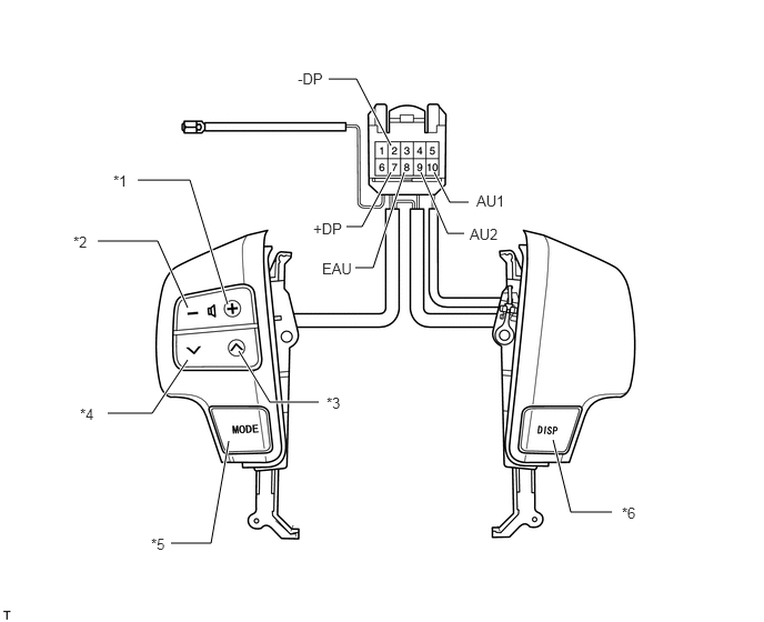
Hide 84250A 3.INSPECT STEERING PAD SWITCH ASSEMBLY (w/ AUDIO + DISP Switch)

a.

Disconnect the z36 switch connector.

E155692E06
3.792,1.615 3.5,2.51 3.5,2.51 3.333,2.51 true 3.948,1.615 4.198,2.188 4.198,2.188 4.354,2.188 true 4.073,1.615 4.219,1.896 4.219,1.896 4.396,1.896 true 2.135,2.854 1.781,1.688 1.781,1.688 1.292,1.688 true 1.76,2.885 1.479,2.26 1.479,2.26 0.917,2.26 true 1.76,3.375 1.427,3.875 1.427,3.875 1.01,3.875 true 2.24,3.292 2.531,3.771 2.531,3.771 2.99,3.771 true 2.146,4.135 1.979,5.094 1.979,5.094 1.604,5.094 true 5.188,4.125 5.354,4.802 5.354,4.802 5.74,4.802 true 3.667,1.365 3.344,0.74 3.344,0.74 3.083,0.74 true 3.25,2.125 3.396,2.125 3.396,2.125 3.667,1.615 true 3.021,2.438 3.333,2.583 0.313,0.146 10 false EAU 4.406,2.115 4.76,2.313 0.354,0.198 10 false AU2 4.469,1.802 4.802,2.021 0.333,0.219 10 false AU1 1.063,1.615 1.302,1.781 0.24,0.167 10 false *1 0.688,2.188 0.99,2.385 0.302,0.198 10 false *2 3.063,3.698 3.323,3.865 0.26,0.167 10 false *3 0.75,3.802 0.979,3.99 0.229,0.188 10 false *4 1.417,5.021 1.677,5.25 0.26,0.229 10 false *5 5.833,4.729 6.198,4.927 0.365,0.198 10 false *6 2.792,0.656 3.219,0.906 0.427,0.25 10 false -DP 2.938,2.063 3.365,2.313 0.427,0.25 10 false +DP

Text in Illustration
*1 Volume+ Switch *2 Volume- Switch
*3 Seek+ Switch *4 Seek- Switch
*5 MODE Switch *6 DISP Switch

Measure the resistance according to the value(s) in the table below.

Standard Resistance:
Tester Connection Switch Condition Specified Condition
10 (AU1) - 8 (EAU) No switch is pushed 100 kΩ
Seek+ switch pushed Below 2.5 Ω
Seek- switch pushed 329 Ω
Volume+ switch pushed 1000 Ω
Volume- switch pushed 3110 Ω
9 (AU2) - 8 (EAU) No switch is pushed 100 kΩ
MODE switch pushed Below 2.5 Ω
2 (-DP) - 7 (+DP) DISP switch pushed Below 2.5 Ω


If the result is not as specified, replace the steering pad switch assembly.


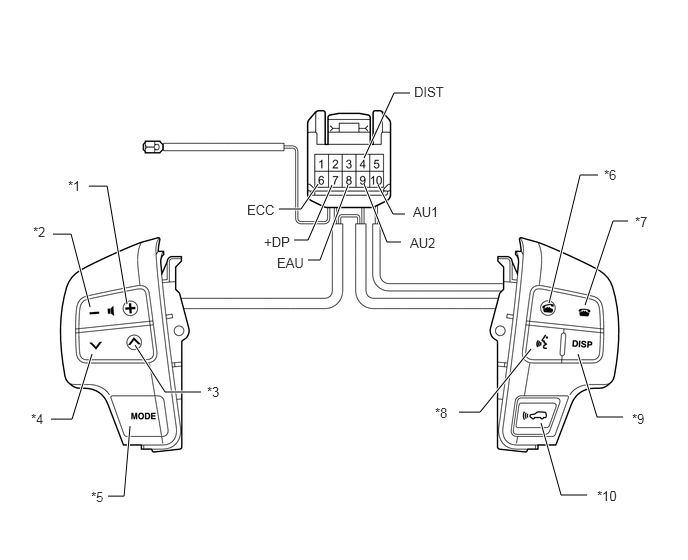
Hide 84250A 4.INSPECT STEERING PAD SWITCH ASSEMBLY (w/ AUDIO + TEL + VOICE + DISP + Distance Control Switch)

a.

Disconnect the z36 switch connector.

E158677E03
3.458,1.927 3.208,2.5 3.208,2.5 3.063,2.5 true 3.313,1.917 3.135,2.177 3.135,2.177 2.906,2.177 true 3.625,1.927 3.333,2.708 3.333,2.708 3.208,2.708 true 3.792,1.646 4.104,0.969 4.104,0.969 4.271,0.969 true 3.938,1.927 4.094,2.229 4.094,2.229 4.219,2.229 true 1.323,3.167 1.115,1.938 1.115,1.938 0.927,1.938 true 0.938,3.198 0.74,2.438 0.74,2.438 0.552,2.438 true 1.406,3.594 1.719,4.083 1.719,4.083 2.094,4.083 true 0.958,3.688 0.75,4.365 0.75,4.365 0.531,4.365 true 1.354,4.438 1.292,5.167 1.292,5.167 1.125,5.167 true 5.719,3.156 6.042,1.823 6.042,1.823 6.229,1.823 true 6.094,3.177 6.385,2.302 6.385,2.302 6.542,2.302 true 5.531,3.635 5,4.292 5,4.292 4.781,4.292 true 6.021,3.688 6.219,4.344 6.219,4.344 6.49,4.344 true 5.635,4.406 5.844,5.156 5.844,5.156 6.115,5.156 true 3.792,1.917 4.031,2.521 4.031,2.521 4.177,2.521 true 2.75,2.438 3.135,2.635 0.385,0.198 10 false +DP 2.573,2.104 2.938,2.302 0.365,0.198 10 false ECC 2.885,2.656 3.271,2.844 0.385,0.188 10 false EAU 4.313,0.875 4.667,1.063 0.354,0.188 10 false DIST 4.271,2.448 4.625,2.646 0.354,0.198 10 false AU2 4.302,2.125 4.719,2.365 0.417,0.24 10 false AU1 0.708,1.854 1.01,2.042 0.302,0.188 10 false *1 0.344,2.333 0.646,2.531 0.302,0.198 10 false *2 2.156,4 2.49,4.177 0.333,0.177 10 false *3 0.323,4.281 0.563,4.469 0.24,0.188 10 false *4 0.948,5.094 1.167,5.313 0.219,0.219 10 false *5 6.615,2.229 6.885,2.406 0.271,0.177 10 false *7 6.292,1.74 6.563,1.917 0.271,0.177 10 false *6 4.531,4.219 4.802,4.427 0.271,0.208 10 false *8 6.583,4.281 6.865,4.49 0.281,0.208 10 false *9 6.219,5.083 6.635,5.26 0.417,0.177 10 false *10

Text in Illustration
*1 Volume+ Switch *2 Volume- Switch
*3 Seek+ Switch *4 Seek- Switch
*5 MODE Switch *6 Off Hook Switch
*7 On Hook Switch *8 Voice Switch
*9 DISP Switch *10 Distance Control Switch

Measure the resistance according to the value(s) in the table below.

Standard Resistance:
Tester Connection Switch Condition Specified Condition
10 (AU1) - 8 (EAU) No switch is pushed 100 kΩ
Seek+ switch pushed Below 2.5 Ω
Seek- switch pushed 329 Ω
Volume+ switch pushed 1000 Ω
Volume- switch pushed 3110 Ω
9 (AU2) - 8 (EAU) No switch is pushed 100 kΩ
MODE switch pushed Below 2.5 Ω
ON Hook switch pushed 329 Ω
OFF Hook switch pushed 1000 Ω
Voice switch pushed 3110 Ω
7 (+DP) - 8 (EAU) DISP switch pushed Below 2.5 Ω
4 (DIST) - 6 (ECC) Distance Control Switch pushed Below 2.5 Ω


If the result is not as specified, replace the steering switch assembly.


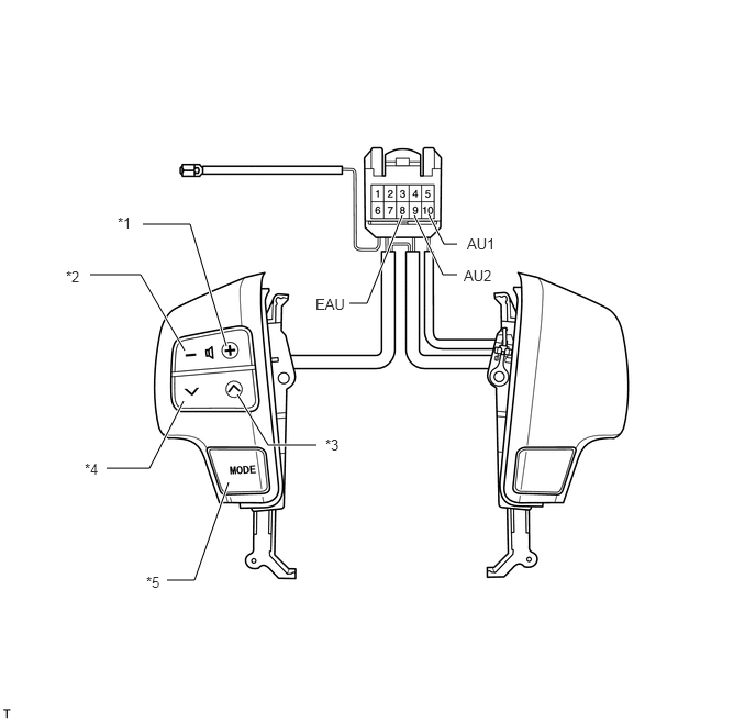
Hide 84250A 5.INSPECT STEERING PAD SWITCH ASSEMBLY (w/ AUDIO Switch)

a.

Disconnect the z36 switch connector.

C226741E02
2.146,3.281 1.802,2.125 1.802,2.125 1.354,2.125 true 1.75,3.323 1.333,2.604 1.333,2.604 0.854,2.604 true 1.74,3.802 1.417,4.438 1.417,4.438 1.01,4.438 true 2.25,3.74 2.542,4.219 2.542,4.219 3,4.219 true 2.167,4.573 1.844,5.5 1.844,5.5 1.583,5.5 true 3.813,2.042 3.479,2.875 3.479,2.875 3.313,2.875 true 3.927,2.042 4.198,2.604 4.198,2.604 4.333,2.604 true 4.063,2.031 4.208,2.313 4.208,2.313 4.333,2.313 true 2.99,2.802 3.344,2.979 0.354,0.177 10 false EAU 4.396,2.531 4.76,2.719 0.365,0.188 10 false AU2 4.427,2.229 4.792,2.458 0.365,0.229 10 false AU1 1.115,2.031 1.323,2.219 0.208,0.188 10 false *1 0.625,2.542 0.896,2.771 0.271,0.229 10 false *2 3.083,4.135 3.323,4.344 0.24,0.208 10 false *3 0.802,4.365 1.104,4.573 0.302,0.208 10 false *4 1.385,5.438 1.635,5.677 0.25,0.24 10 false *5

Text in Illustration
*1 Volume+ Switch *2 Volume- Switch
*3 Seek+ Switch *4 Seek- Switch
*5 MODE Switch - -

Measure the resistance according to the value(s) in the table below.

Standard Resistance:
Tester Connection Switch Condition Specified Condition
10 (AU1) - 8 (EAU) No switch is pushed 100 kΩ
Seek+ switch pushed Below 2.5 Ω
Seek- switch pushed 329 Ω
Volume+ switch pushed 1000 Ω
Volume- switch pushed 3110 Ω
9 (AU2) - 8 (EAU) No switch is pushed 100 kΩ
MODE switch pushed Below 2.5 Ω


If the result is not as specified, replace the steering switch assembly.