RM2660E
_55
Steering
_052826
STEERING COLUMN
_0255461
STEERING HEATER SWITCH
G
STEERING COLUMN STEERING HEATER SWITCH INSPECTION
PROCEDURE

 84255
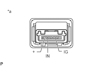
1.INSPECT STEERING HEATER SWITCH
a.
1.229,1.719 1.354,1.719
1.354,1.719 1.49,1.281
true
1.594,1.281 1.594,1.75
true
2.063,1.698 1.969,1.698
1.969,1.698 1.854,1.281
true
1.083,1.625 1.208,1.792
0.125,0.167
10
false
+
1.521,1.771 1.729,1.938
0.208,0.167
10
false
IN
2.125,1.635 2.375,1.823
0.25,0.188
10
false
IG
0.25,0.292 0.458,0.479
0.208,0.188
10
false
*a
Disconnect the steering heater switch connector.
b.
Measure the voltage according to the value(s) in the table below.
- HINT:
-
As the circuit has a diode, perform the measurement in diode test mode, and do not mistake the polarity.
- Standard Voltage:
Tester Connection
(Positive (+) tester probe - Negative (-) tester probe)Condition Specified Condition 3 (IG) - 7 (+) Always Below 1.25 V 6 (IN) - 7 (+) Steering heater switch is pushed Below 1.25 V
c.
Measure the resistance according to the value(s) in the table below.
- Standard Resistance:
Tester Connection Condition Specified Condition 3 (IG) - 6 (IN) Steering heater switch is pushed Below 1 Ω 3 (IG) - 6 (IN) Steering heater switch is not pushed 10 kΩ or higher
| *a | Component without harness connected
(Steering Heater Switch) |