STEERING GEAR / LINKAGE STEERING LINKAGE REASSEMBLY
CAUTION / NOTICE / HINT
- HINT:
- ·
Use the same procedure for RHD and LHD vehicles.
·The procedure listed below is for LHD vehicles.
PROCEDURE

 45503
1.INSTALL STEERING RACK END SUB-ASSEMBLY
Temporarily install the 2 steering rack ends to the power steering rack.
Fill up the ball joint of the steering rack ends with MP grease.
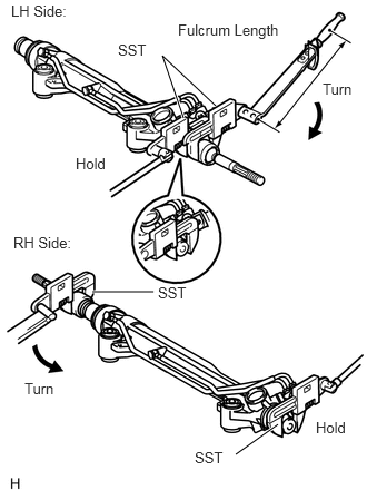
Using SST, tighten the power steering rack end (RH side) to the power steering rack.
- SST
- 09922-10010
- Torque:
- without SST : 147 N*m (1499 kgf*cm, 108 ft.*lbf)
- with SST : 110 N*m (1122 kgf*cm, 81 ft.*lbf)
- HINT:
- ·
Rotate SST in the direction shown in the illustration.
·Use a torque wrench with a fulcrum length of 380 mm (14.97 in.).
Using SST, tighten the power steering rack end (LH side) to the power steering rack.
- SST
- 09922-10010
- Torque:
- without SST : 147 N*m (1499 kgf*cm, 108 ft.*lbf)
- with SST : 110 N*m (1122 kgf*cm, 81 ft.*lbf)
- HINT:
- ·
Rotate SST in the direction shown in the illustration.
·Use a torque wrench with a fulcrum length of 380 mm (14.97 in.).
45535
2.INSTALL NO. 1 STEERING RACK BOOT
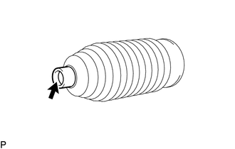
Apply silicon grease to the inside of the small opening of the boot.
Install the 2 boots to the groove on the rack housing.
3.INSTALL STEERING RACK BOOT CLAMP RH
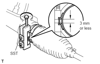
Using SST, install a new boot clamp as shown in the illustration.
- SST
- 09521-24010
- Standard clearance:
3.0 mm (0.119 in.) or less
- NOTICE:
-
Be careful not to damage the boot.
4.INSTALL STEERING RACK BOOT CLAMP LH
- HINT:
-
Use the same procedures described for the RH side.
5.INSTALL STEERING RACK BOOT CLIP RH
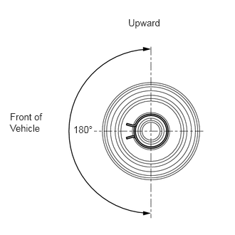
Using pliers, install the boot clip.
- NOTICE:
-
Make sure that the claws of each clip are positioned within the area shown in the illustration.
6.INSTALL STEERING RACK BOOT CLIP LH
- HINT:
-
Use the same procedures described for the RH side.